CAN SPI Click 5V
R440.00 ex. VAT
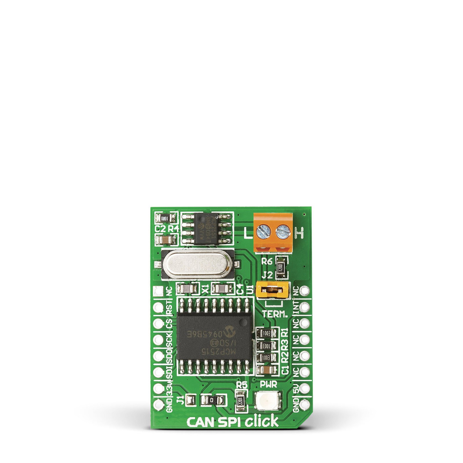
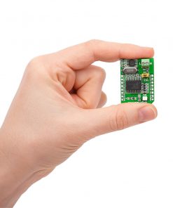
CAN SPI Click 5V is a compact add-on board that provides a complete CAN solution and can be used as a control node in a CAN network. This board features the MCP2515, a stand-alone CAN controller with an SPI interface from Microchip. This Click board™ also uses the SN65HVD230, a CAN Bus transceiver from Texas Instruments, as an interface between an MCP2515 CAN protocol controller and the physical two-wire CAN bus. This Click board™ makes the perfect solution for developing industrial automation, home automation, and the automotive and mobile machine industry.
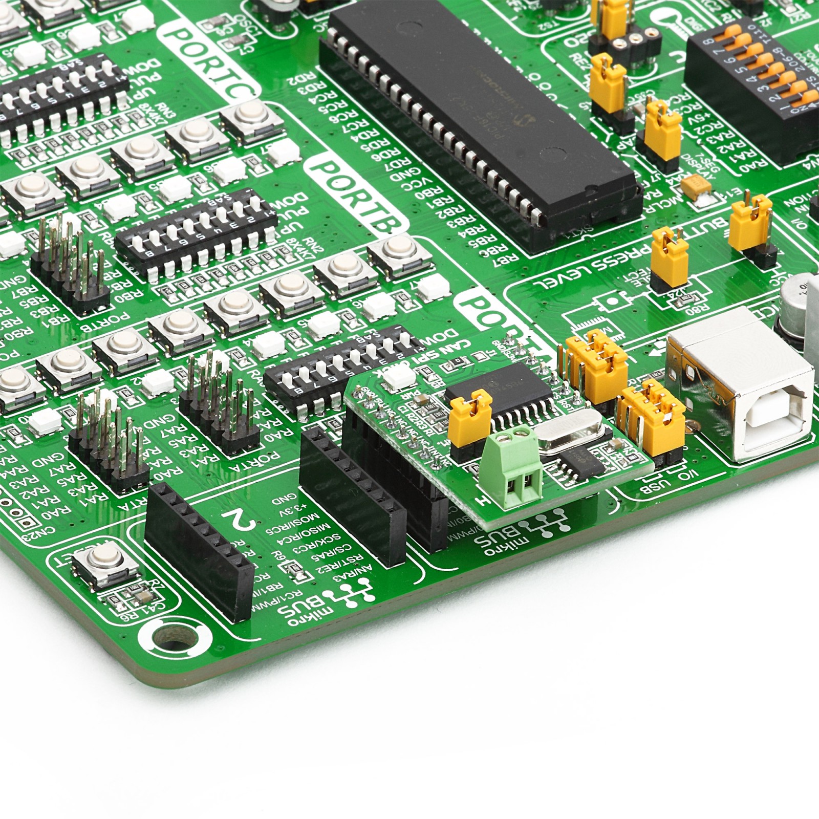
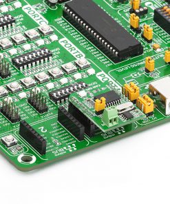
CAN SPI Click 5V is supported by a mikroSDK compliant library, which includes functions that simplify software development. This Click board™ comes as a fully tested product, ready to be used on a system equipped with the mikroBUS™ socket.
Stock: Lead-time applicable.
| 5+ | R418.00 |
| 10+ | R396.00 |
| 15+ | R374.00 |
| 20+ | R359.92 |
How does it work?
CAN SPI Click 5V is based on the MCP2515, a standalone CAN controller with an SPI interface from Microchip. It implements CAN V2.0B at 1Mbps, capable of transmitting and receiving standard and extended data and remote frames. It features two receive buffers, six 29-bit acceptance filters, and two 29-bit acceptance masks to filter out unwanted messages, thus reducing the host MCU load. Data byte filtering is done on the two first data bytes. In addition, there are three transmit buffers that prioritize and abort the messages.
According to the CAN 2.0B specification, the MCP2515 supports a Standard, Extended, and Remote Data frame. It also comes with an Error frame, an Overload frame, and an Interframe Space. The last one separates a preceding frame of any type from subsequent data or a remote frame. In message transmissions, we distinguish transmit buffers, transmit priority, initiating transmission, One-shot mode, and aborting transmission. There are five modes of operation: Configuration mode, Normal mode, Sleep mode, Listen-only mode, and Loopback mode. No matter the changed mode, the MCP2515 will complete all pending operations.
To communicate with the host MCU, CAN SPI Click 5V uses a standard 4-wire SPI serial interface supporting Mode 0 and Mode 3, with speeds up to 10MHz. The RST pin is available for resetting the CAN controller. The interrupt message will be generated on the INT pin, depending on the status. The CAN protocol engine pins TXCAN and RXCAN of the MCP2515 are routed to the screw terminal of the CAN Bus via the SN65HVD230. This transceiver adds a physical layer to the CAN Bus controller. In addition, it also adds ESD protection, high impedance allowing up to 120 nodes to the Bus, thermal shutdown protection, and is designed for data rates of up to 1Mbps.
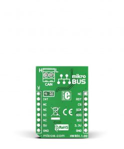
There is a node termination jumper under the CAN screw terminal labeled with plus and minus signs for CANH and CANL. If the board is the CAN network’s first and last node, then the J2 jumper should be placed. Otherwise, this jumper should be removed if the board is in the middle.
This Click board™ can be operated only with a 5V logic voltage level. The board must perform appropriate logic voltage level conversion before using MCUs with different logic levels. However, the Click board™ comes equipped with a library containing functions and an example code that can be used, as a reference, for further development.
Specifications
Type
CAN
Applications
Can be used for the development of industrial automation, and home automation as well as in the automotive and mobile machine industry
On-board modules
MCP2515 – standalone CAN controller from Microchip
SN65HVD230 – CAN bus transceiver from Texas Instruments
Key Features
CAN controller, CAN transceiver, standalone CAN device, node termination option, low Standby current, 2.0B CAN standard, ESD protection, thermal shutdown protection, open circuit fail-safe design, and more
Interface
GPIO,SPI
Feature
No ClickID
Compatibility
mikroBUS™
Click board size
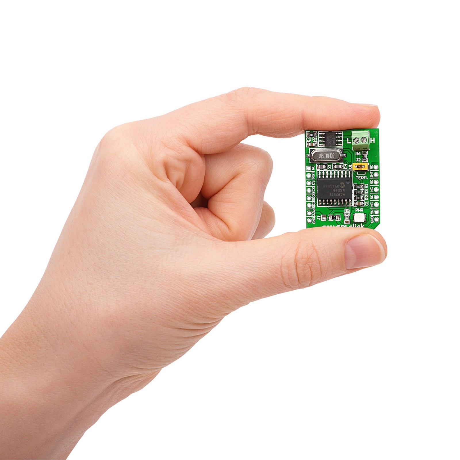
M (42.9 x 25.4 mm)
Input Voltage
5V
Pinout diagram
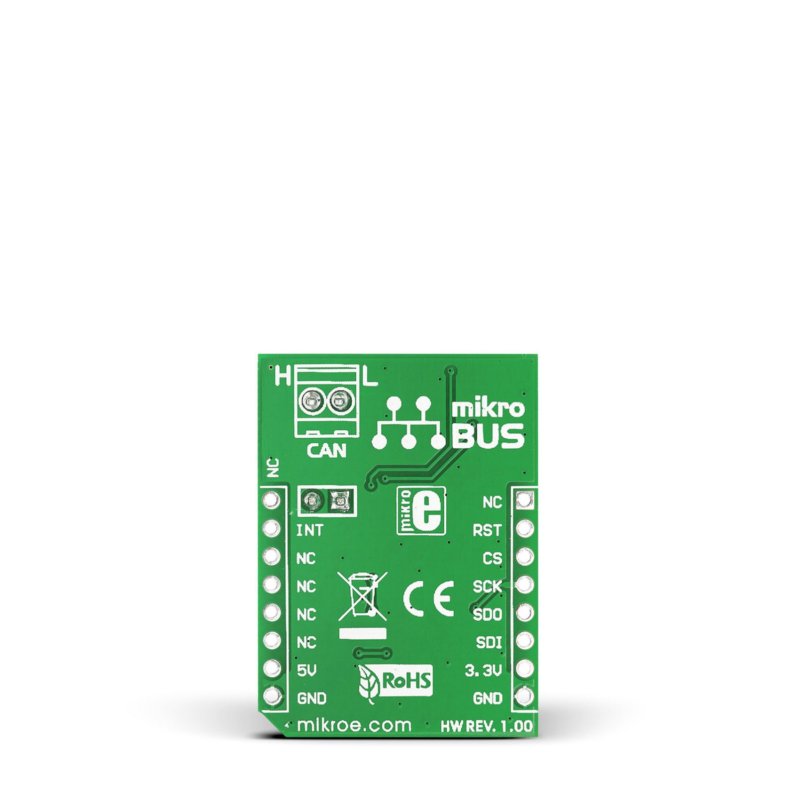
This table shows how the pinout on CAN SPI Click 5V Click corresponds to the pinout on the mikroBUS™ socket (the latter shown in the two middle columns).
Onboard settings and indicators
| Label | Name | Default | Description |
|---|---|---|---|
| LD1 | PWR | – | Power LED Indicator |
| – | TERM. | Populated | Node Termination Jumper |
CAN SPI Click 5V electrical specifications
| Description | Min | Typ | Max | Unit |
|---|---|---|---|---|
| Supply Voltage | – | 5 | – | V |
| Data Rate | – | – | 1 | Mbps |
| ESD Protection | – | ±16 | – | kV |
Software Support
We provide a library for the CAN SPI Click 5V on our LibStock page, as well as a demo application (example), developed using MIKROE compilers. The demo can run on all the main MIKROE development boards.
Library Description
The library covers all the necessary functions to control CAN SPI 5v click board.
Key functions:
void canspi5v_hwReset()– Hardware reset function.uint8_t canspi5v_getInterrupt()– Get interrupt state function.
Examples description
The application is composed of three sections :
- System Initialization – Initializes GPIO, SPI, and LOG structures, sets INT pin as input, CS and RST pin as output and start to write log.
- Application Initialization – Initialization driver enables – SPI, initialize external CANSPI module, also write log.
- Application Task – (code snippet) This is an example which demonstrates the use of CAN SPI 5v Click board. In this example, we shows simple connection of two CAN SPI 5v modules. Results are being sent to the Usart Terminal where you can track their changes. All data logs write on usb uart changes for every 1 sec.
void applicationTask()
{
    char dataRxTx[ 8 ];
    uint8_t dataRxLen;
    uint8_t msgRcvd;
    uint8_t dataTx;
    uint32_t idRx;

    dataTx = 0xAB;

    msgRcvd = CANSPIRead( &idRx , &dataRxTx , &dataRxLen, &canRcvFlags );

    if ( msgRcvd )
    {
        mikrobus_logWrite( &dataRxTx, _LOG_BYTE );
        Delay_1sec();
    }

//    CANSPIWrite( id2nd, dataTx, 1, canSendFlags );
//    mikrobus_logWrite( "MESSAGE SENT", _LOG_LINE );
//    Delay_1sec();
}
The full application code, and ready to use projects can be found on our LibStock page.
Other mikroE Libraries used in the example:
- SPI
- CAN_SPI
- UART
Additional notes and informations
Depending on the development board you are using, you may need USB UART click, USB UART 2 click or RS232 click to connect to your PC, for development systems with no UART to USB interface available on the board. The terminal available in all MIKROE compilers, or any other terminal application of your choice, can be used to read the message.
mikroSDK
This Click board™ is supported with mikroSDK – MIKROE Software Development Kit. To ensure proper operation of mikroSDK compliant Click board™ demo applications, mikroSDK should be downloaded from the LibStock and installed for the compiler you are using.
For more information about mikroSDK, visit the official page.
Resources
Downloads
| Weight | 28 g |
|---|---|
| Brand | MikroElektronika |

