How does it work?
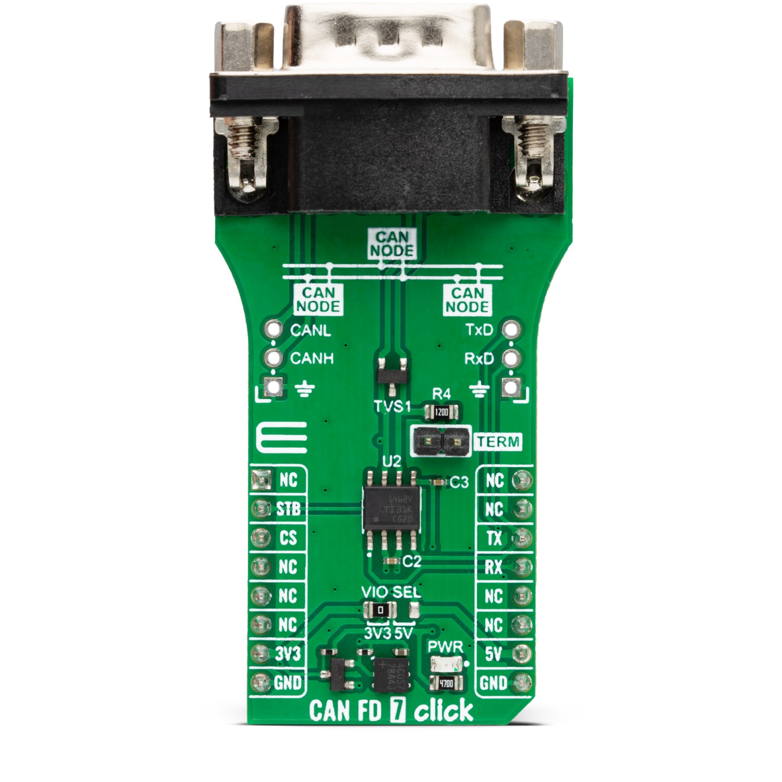
CAN FD 7 Click is based on the TCAN1462, an automotive fault-protected CAN FD transceiver from Texas Instruments. The transceiver is data rate agnostic, making it backward compatible for supporting classical CAN applications while also supporting CAN FD networks up to 8 Mbps. It actively improves the bus signal by reducing ringing effects in complex topologies, enabling higher throughput. In addition, the transceiver has a much tighter bit of timing symmetry, which provides a larger timing window to sample the correct bit and enables error-free communication in large complex star networks where ringing and bit distortion are inherent. It also has a passive behavior when unpowered and supports a hot plug, with power up or down glitch-free operation. As for protection, the transceiver features IEC ESD protection, under-voltage, thermal shutdown, TXD dominant state timeout, and more.
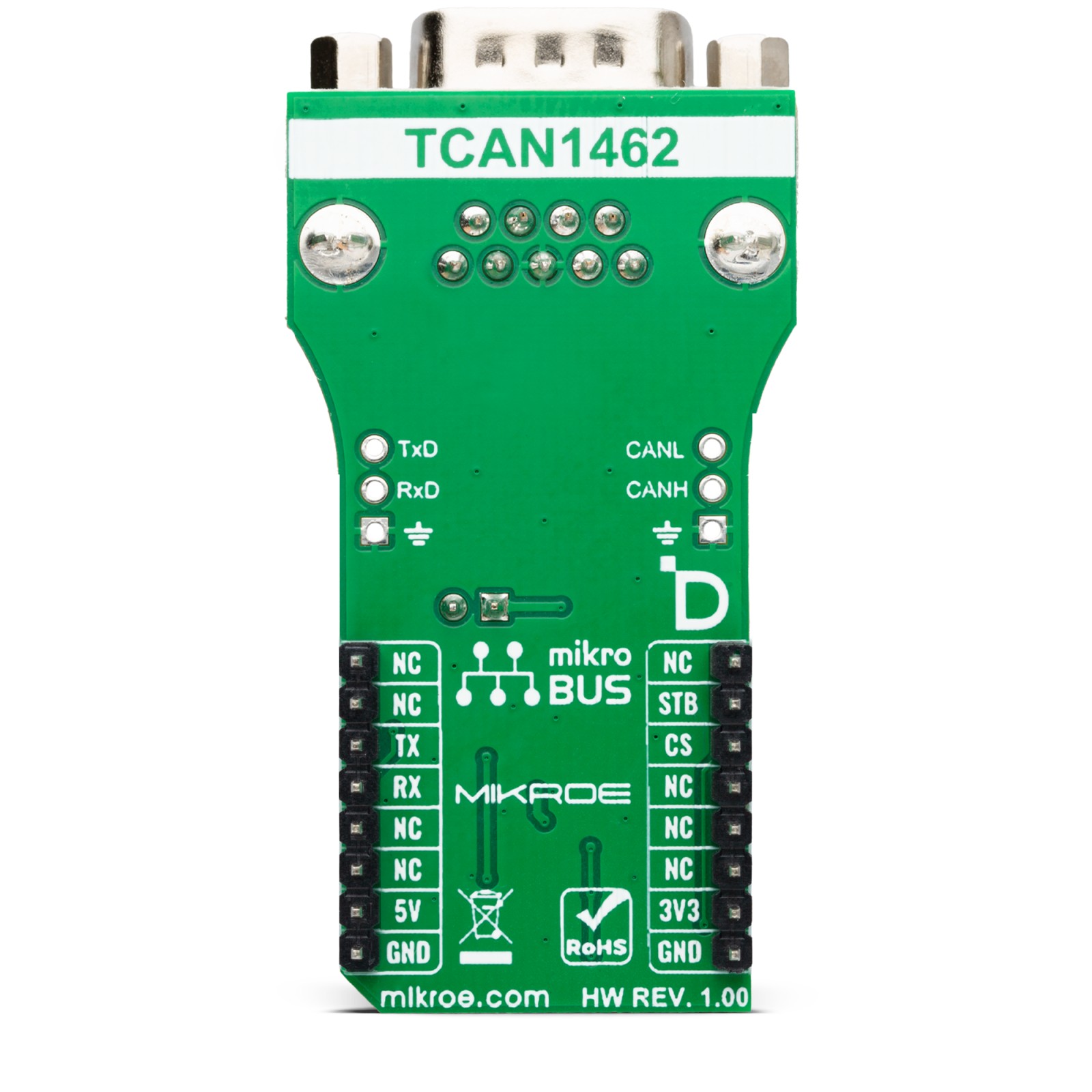
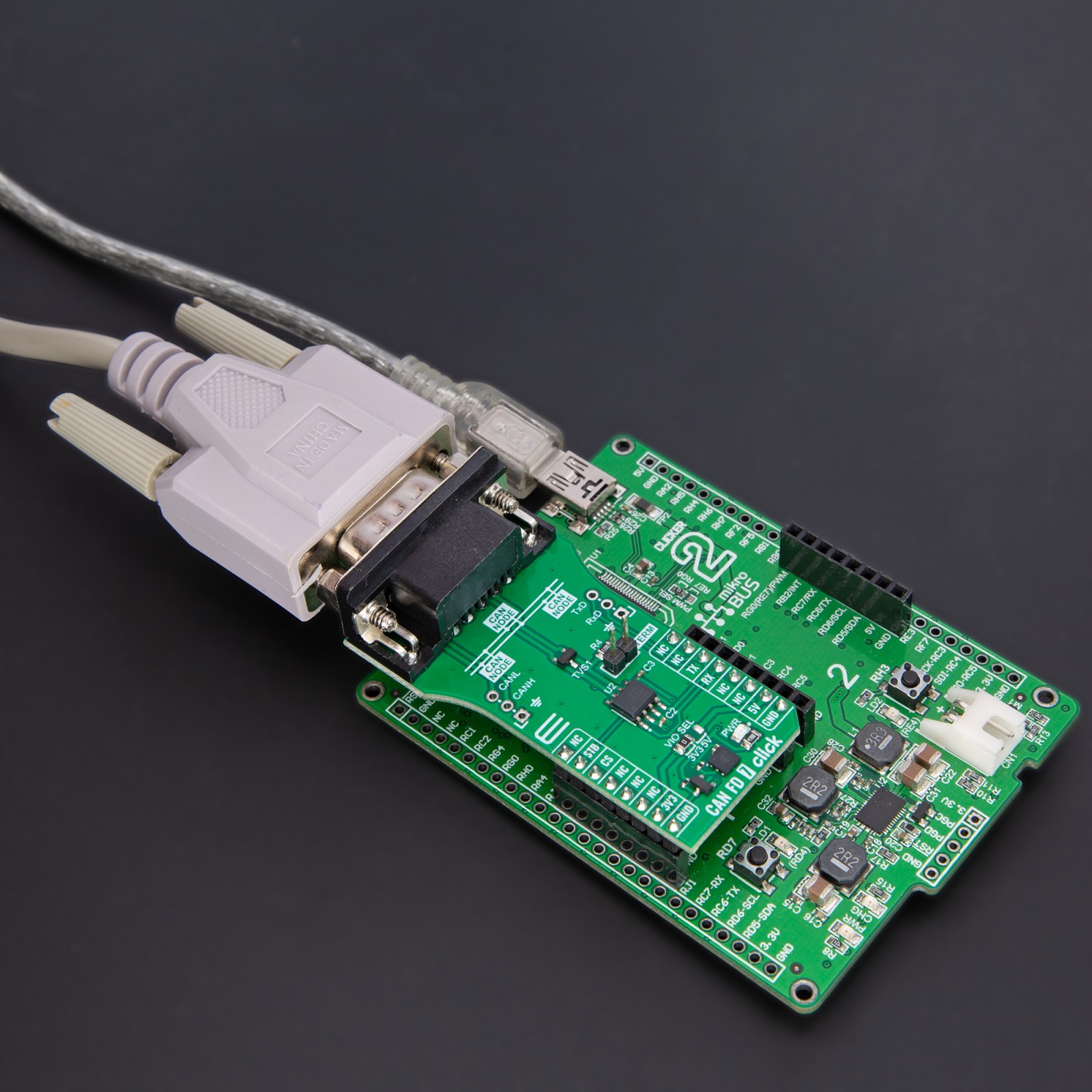
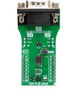
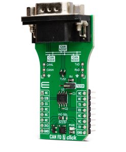
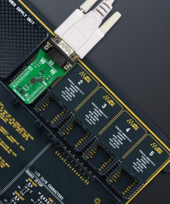
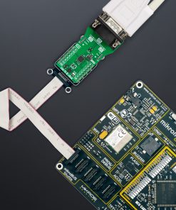
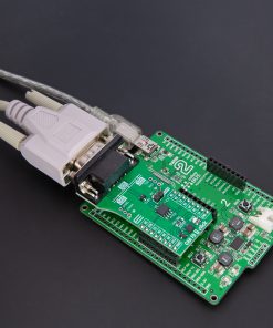
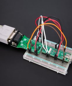
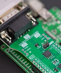
This Click board™ comes equipped with the industry-standard DE-9 connector, making interfacing with the CAN bus simple and easy. Besides, the user can connect the CAN signals directly through the CAN External header located on the board’s left edge (unpopulated by default). The same goes for the UART signals over the TXD/RXD header. The termination 120Ω resistor labeled TERM allows CAN termination to the bus, which you can disable.
CAN FD 7 Click uses a standard UART interface to communicate with the host MCU with commonly used UART RX and TX pins. Besides the normal mode, the transceiver has standby mode support, which puts the transceiver in ultra-low current consumption mode, which, upon receiving a valid wake-up pattern (WUP) on the CAN bus, signals to the microcontroller through the RXD pin. The MCU can then put the device into normal mode using the standby mode STB input pin.
This Click board™ can operate with either 3.3V or 5V logic voltage levels selected via the VIO SEL jumper. This way, both 3.3V and 5V capable MCUs can use the communication lines properly. Also, this Click board™ comes equipped with a library containing easy-to-use functions and an example code that can be used as a reference for further development.
Specifications
Type
CAN
Applications
Can be used for the development of automotive gateways, advanced driver assistant systems (ADAS), body electronics and lighting, hybrid, electric, and power-train systems, and more
On-board modules
TCAN1462 – automotive fault-protected CAN FD transceiver from Texas Instruments
Key Features
CAN FD transceiver, meets the requirements of ISO 11898-2:2016, and CiA 601-4 standards, high data rate in large networks with multiple unterminated stubs, standby mode supporting the remote wake-up request, passive behavior when unpowered, several protection features, and more
Interface
UART
Feature
ClickID
Compatibility
mikroBUS™
Click board size
L (57.15 x 25.4 mm)
Input Voltage
3.3V or 5V
Pinout diagram
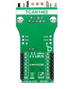
This table shows how the pinout on CAN FD 7 Click corresponds to the pinout on the mikroBUS™ socket (the latter shown in the two middle columns).
Onboard settings and indicators
Label | Name | Default | Description |
---|---|---|---|
LD1 | PWR | – | Power LED Indicator |
JP1 | VIO SEL | Left | Logic Level Voltage Selection 3V3/5V: Left position 3V3, Right position 5V |
J1 | VIO SEL | TERM | Unpopulated Termination Resistor Selection |
CAN FD 7 Click electrical specifications
Description | Min | Typ | Max | Unit |
---|---|---|---|---|
Supply Voltage | – | 5 | – | V |
CAN FD Data Rate | – | – | 8 | Mbps |
Software Support
We provide a library for the CAN FD 7 Click as well as a demo application (example), developed using MIKROE compilers. The demo can run on all the main MIKROE development boards.
Package can be downloaded/installed directly from NECTO Studio Package Manager (recommended), downloaded from our LibStock™ or found on Mikroe github account.
Library Description
This library contains API for CAN FD 7 Click driver.
Key functions
-
canfd7_generic_write
CAN FD 7 data writing function. -
canfd7_generic_read
CAN FD 7 data reading function. -
canfd7_set_stb_pin
CAN FD 7 set STB pin function.
Example Description
This example writes and reads and processes data from CAN FD 7 Click. The library also includes a function for selection of the output polarity.
void application_task ( void )
{
#ifdef DEMO_APP_TRANSMITTER
canfd7_generic_write( &canfd7, TX_MESSAGE, strlen( TX_MESSAGE ) );
log_info( &logger, "---- Data sent ----" );
Delay_ms( 2000 );
#else
canfd7_process( &canfd7 );
#endif
}
The full application code, and ready to use projects can be installed directly from NECTO Studio Package Manager (recommended), downloaded from our LibStock™ or found on Mikroe github account.
Other Mikroe Libraries used in the example:
- MikroSDK.Board
- MikroSDK.Log
- Click.CANFD7
Additional notes and informations
Depending on the development board you are using, you may need USB UART click, USB UART 2 Click or RS232 Click to connect to your PC, for development systems with no UART to USB interface available on the board. UART terminal is available in all MIKROE compilers.
mikroSDK
This Click board™ is supported with mikroSDK – MIKROE Software Development Kit. To ensure proper operation of mikroSDK compliant Click board™ demo applications, mikroSDK should be downloaded from the LibStock and installed for the compiler you are using.
For more information about mikroSDK, visit the official page.