How does it work?
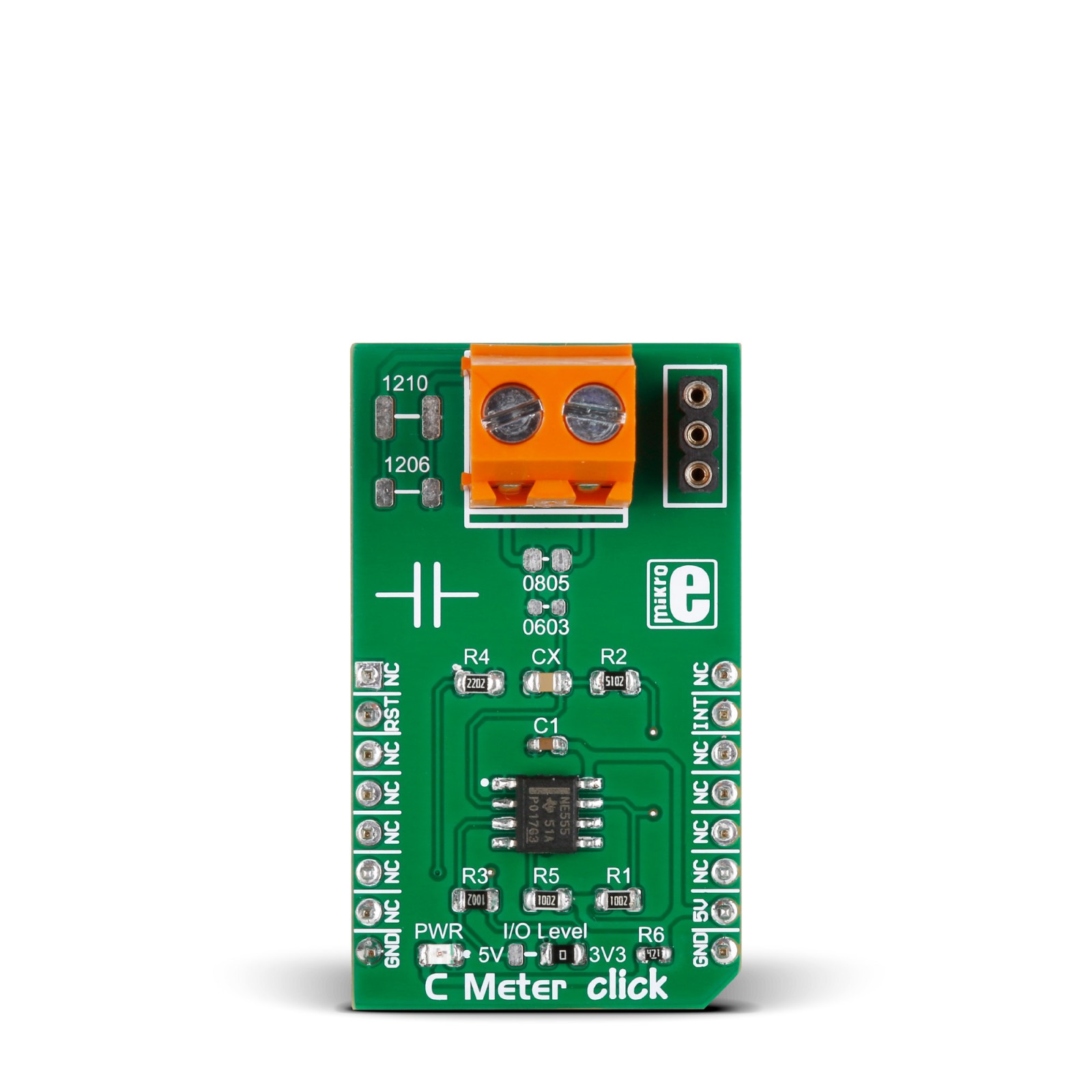
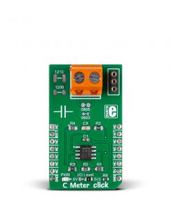
C Meter Click is based on the NE-555, a precision timer from Texas Instruments. The NE-555 is the most famous, most recognized integral circuit out there. It has two modes of operation, astable and monostable, where the first one is used on this Click board™ to get the values of the capacitors. The board outputs a square frequency, and depending on the capacitor placed on the board, the value of this frequency changes. The value of a capacitor can be inferred using a simple algorithm. The 3-pin socket can hold any PTH capacitor, and to note, the positive pin of the capacitors must be inserted in the middle, while the negative can be inserted in any of the outside pin sockets. Regarding the SMD, the C Meter has four SMD plates to measure the standard capacitor sizes of 1210, 1206, 0805, and 0603 in standard imperial measurements.
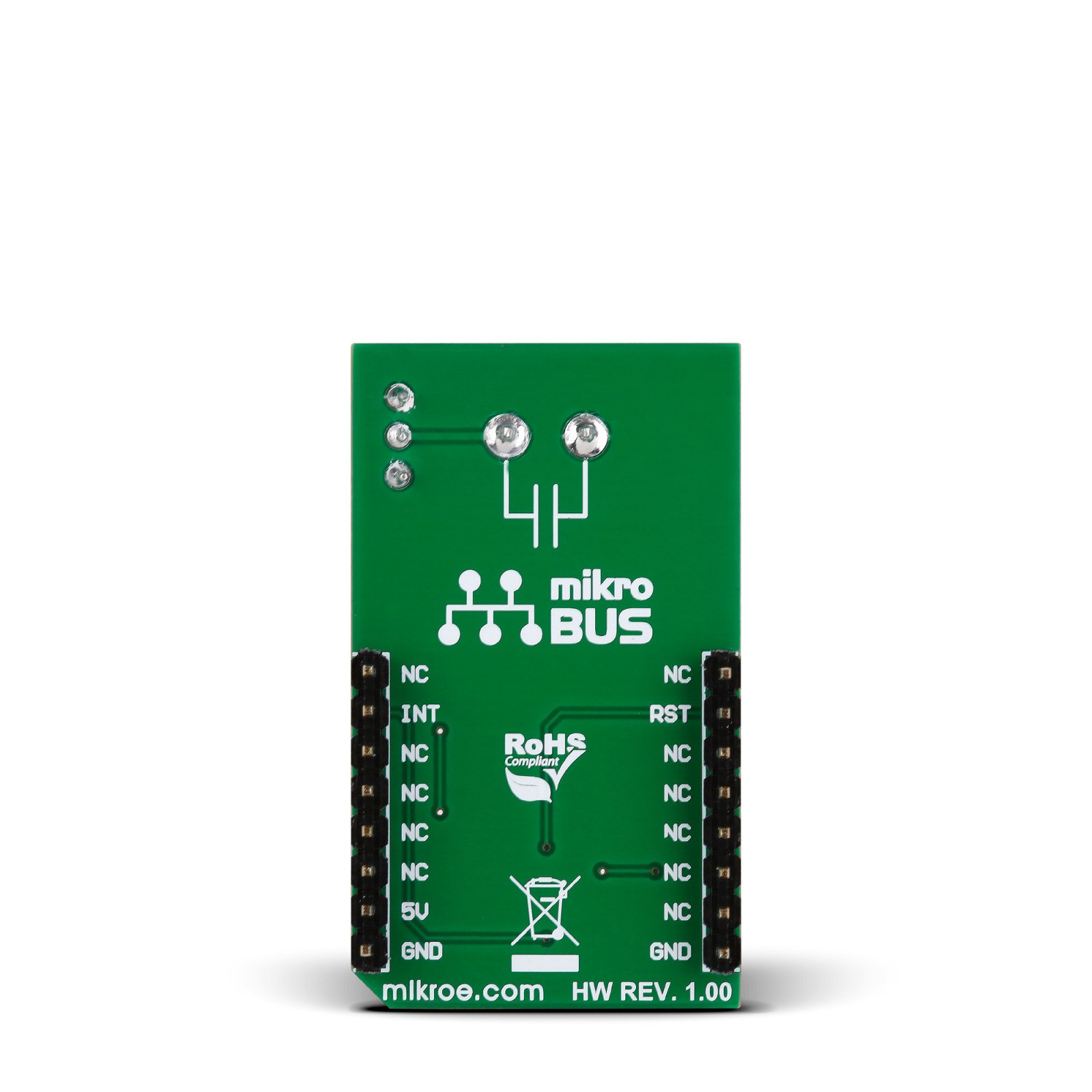
As the output of this Click board™ is a square wave frequency, it communicates with the host MCU over an interrupt INT pin of the mikroBUS™ socket. Although the C Meter Click is designed to use a 5V power supply only, it can process interrupt with either a 3.3V or 5V logic level. The logic level can be selected over the I/O Level jumper, with 3V3 selected by default. In addition, C Meter Click features the reset RST pin that forces output and discharge low.
This Click board™ can only be operated with a 5V logic voltage level. The board must perform appropriate logic voltage level conversion before using MCUs with different logic levels. However, the Click board™ comes equipped with a library containing functions and an example code that can be used as a reference for further development.
Specifications
Type
Measurements
Applications
Can be used for the development of applications based on capacitance measurements, tools, and more
On-board modules
NE-555 – precision timer from Texas Instruments
Key Features
Four plates for measurement of the SMD capacitors labeled 1210, 1206, 0805, and 0603 as a standard SMD package size, a PTH socket for measurement thru-hole capacitors, a screw terminal for multimeter probes, and more
Interface
GPIO
Feature
No ClickID
Compatibility
mikroBUS™
Click board size
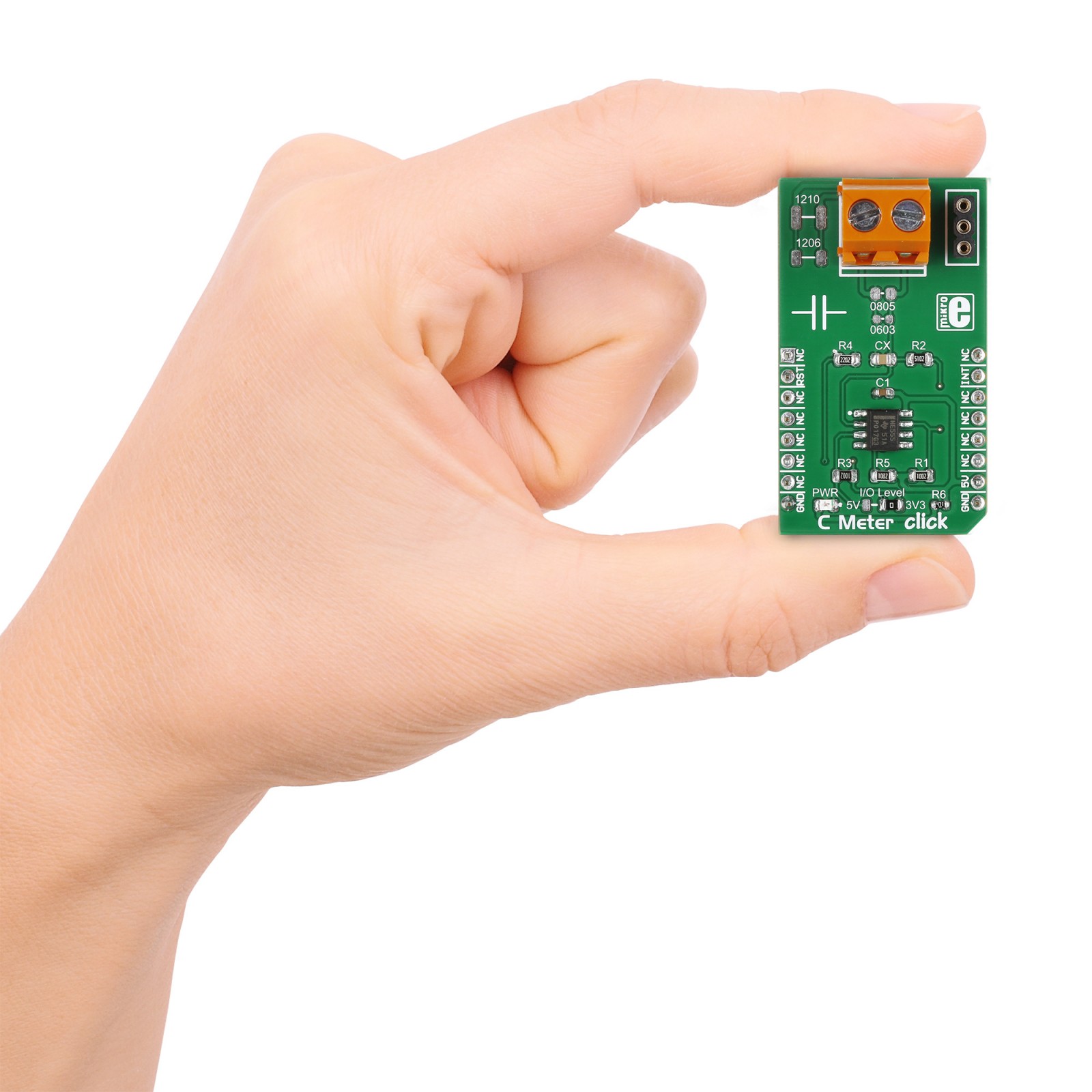
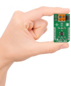
M (42.9 x 25.4 mm)
Input Voltage
3.3V or 5V
Pinout diagram
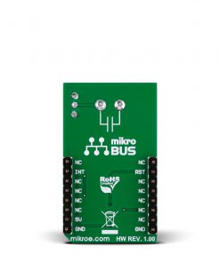
This table shows how the pinout on C Meter Click corresponds to the pinout on the mikroBUS™ socket (the latter shown in the two middle columns).
Onboard settings and indicators
Label | Name | Default | Description |
---|---|---|---|
PWR | PWR | – | Power LED Indicator |
JP1 | I/O Level | Right | Interrupt Signal Voltage Level Selection 5V/3V3: Left position 5V, Right position 3V3 |
C Meter Click electrical specifications
Description | Min | Typ | Max | Unit |
---|---|---|---|---|
Supply Voltage | – | 5 | – | V |