-
×
 DIGI POT Click
1 × R365.00
DIGI POT Click
1 × R365.00 -
×
 EXPAND Click
1 × R255.00
EXPAND Click
1 × R255.00 -
×
 Alcohol 3 Click
1 × R690.00
Alcohol 3 Click
1 × R690.00
Subtotal: R1,310.00
DIGI POT Click
1 × R365.00 EXPAND Click
1 × R255.00 Alcohol 3 Click
1 × R690.00 Subtotal: R1,310.00


R220.00 ex. VAT
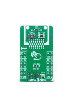
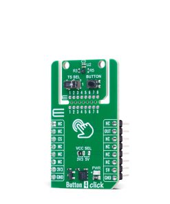
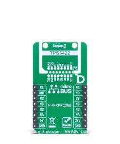
Button 4 Click is a compact add-on board designed to provide controlled and reliable manual system resets in embedded applications. It is based on the TPS3422 push-button reset controller from Texas Instruments, known for its ultra-low power consumption and precision timing features. The board features a programmable delay mechanism that differentiates between brief key presses and intentional resets, helping to prevent accidental resets. It includes the innovative Click Snap format, allowing the main IC area to operate independently and be mounted separately, with a configurable reset delay of 0 or 7.5 seconds via an onboard switch. Button 4 Click is ideal for applications such as gaming consoles, portable consumer electronics, navigation systems, medical devices, and interactive toys.
Button 4 Click is fully compatible with the mikroBUS™ socket and can be used on any host system supporting the mikroBUS™ standard. It comes with the mikroSDK open-source libraries, offering unparalleled flexibility for evaluation and customization. What sets this Click board™ apart is the groundbreaking ClickID feature, enabling your host system to seamlessly and automatically detect and identify this add-on board, alongside a Click Snap feature introducing a new level of flexibility and ease of use.
Stock: Lead-time applicable.
| 5+ | R209.00 |
| 10+ | R198.00 |
| 15+ | R187.00 |
| 20+ | R179.96 |
Button 4 Click is based on the TPS3422, a low-power push-button reset controller from Texas Instruments, designed to distinguish between brief, unintended key presses and deliberate system reset requests. The TPS3422 operates with exceptionally low current consumption and features a programmable delay mechanism that ensures a reset signal is only generated after a button press is maintained for a specific duration. This eliminates false resets caused by accidental or short-duration presses and enables the differentiation between a software interrupt and a true hard reset. The Button 4 Click is an ideal choice for use cases that require controlled reset behavior, such as in gaming consoles, portable consumer electronics, navigation systems, medical devices for consumer use, and various types of interactive toys.

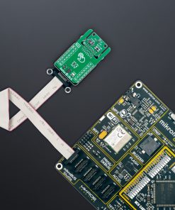
This Click board™ is designed in a unique format supporting the newly introduced MIKROE feature called “Click Snap.” Unlike the standardized version of Click boards, this feature allows the main IC area to become movable by breaking the PCB, opening up many new possibilities for implementation. Thanks to the Snap feature, the TPS3422 can operate autonomously by accessing its signals directly on the pins marked 1-8. Additionally, the Snap part includes a specified and fixed screw hole position, enabling users to secure the Snap board in their desired location.
On the Click Snap section, the push-button labeled as “BUTTON” serves as the user input monitored by the TPS3422. When this button is held down for the duration of the configured delay, the device issues an active-low reset pulse on the OUT pin, which can be routed to a microcontroller or other system component to initiate a reset. The delay time before triggering the reset is configurable via the onboard TS SEL switch. By toggling this switch to position ‘1’, the timer is effectively disabled (0 seconds delay), causing an immediate 400ms reset pulse upon button press. Conversely, setting the switch to position ‘0’ activates a 7.5-second delay, requiring the button to be pressed and held for that full duration before the reset signal is issued, again lasting 400ms.
This Click board™ can operate with either 3.3V or 5V logic voltage levels selected via the VCC SEL jumper. This way, both 3.3V and 5V capable MCUs can use the communication lines properly. Also, this Click board™ comes equipped with a library containing easy-to-use functions and an example code that can be used as a reference for further development.
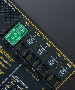
Click Snap is an innovative feature of our standardized Click add-on boards, designed to bring greater flexibility and optimize your prototypes. By simply snapping the PCB along predefined lines, you can easily detach the main sensor/IC/module area, reducing the overall size, weight, and power consumption – ideal for the final phase of prototyping. For more details about Click Snap, visit the official page dedicated to this feature.
Type
Pushbutton/Switches
Applications
Ideal for applications such as gaming consoles, portable consumer electronics, navigation systems, medical devices, and interactive toys
On-board modules
TPS3422 – push-button reset controller from Texas Instruments
Key Features
Low-power push-button reset controller, programmable reset delay, active-low reset pulse output, Click Snap, onboard push-button input, switch for delay configuration, and more
Interface
GPIO
Feature
Click Snap,ClickID
Compatibility
mikroBUS™
Click board size
M (42.9 x 25.4 mm)
Input Voltage
3.3V or 5V
This table shows how the pinout on Button 4 Click corresponds to the pinout on the mikroBUS™ socket (the latter shown in the two middle columns).
| Notes | Pin | Pin | Notes | ||||
|---|---|---|---|---|---|---|---|
| NC | 1 | AN | PWM | 16 | NC | ||
| NC | 2 | RST | INT | 15 | OUT | Active-Low Reset Pulse | |
| ID COMM | CS | 3 | CS | RX | 14 | NC | |
| NC | 4 | SCK | TX | 13 | NC | ||
| NC | 5 | MISO | SCL | 12 | NC | ||
| NC | 6 | MOSI | SDA | 11 | NC | ||
| Power Supply | 3.3V | 7 | 3.3V | 5V | 10 | 5V | Power Supply |
| Ground | GND | 8 | GND | GND | 9 | GND | Ground |
| Label | Name | Default | Description |
|---|---|---|---|
| LD1 | PWR | – | Power LED Indicator |
| JP1 | VCC SEL | Left | Power Voltage Level Selection 3V3/5V: Left position 3V3, Right position 5V |
| T1 | BUTTON | – | User Input Push-Button |
| Description | Min | Typ | Max | Unit |
|---|---|---|---|---|
| Supply Voltage | 3.3 | – | 5 | V |
| Reset Pulse Duration | – | 400 | – | ms |
| Reset Delay | – | – | 7.5 | s |
Button 4 Click demo application is developed using the NECTO Studio, ensuring compatibility with mikroSDK‘s open-source libraries and tools. Designed for plug-and-play implementation and testing, the demo is fully compatible with all development, starter, and mikromedia boards featuring a mikroBUS™ socket.
Example Description
This example demonstrates the use of the Button 4 Click board by initializing the device and detecting the button state changes. It logs whether the button is pressed (active) or released (reset).
Key Functions
button4_cfg_setup This function initializes Click configuration structure to initial values.button4_init This function initializes all necessary pins and peripherals used for this Click board.button4_get_out_pin This function returns the OUT pin logic state.Application Init
Initializes the logger and the Button 4 Click driver.
Application Task
Monitors the button state and logs whether the button is active (pressed) or reset (released) when a state change is detected.
Application Output
This Click board can be interfaced and monitored in two ways:
Additional Notes and Information
The complete application code and a ready-to-use project are available through the NECTO Studio Package Manager for direct installation in the NECTO Studio. The application code can also be found on the MIKROE GitHub account.
| Weight | 17 g |
|---|---|
| Brand | MikroElektronika |