-
×
 METHANE Click
1 × R325.00
METHANE Click
1 × R325.00 -
×
 3D Motion Click
1 × R1,050.00
3D Motion Click
1 × R1,050.00 -
×
 RTC Click
1 × R380.00
RTC Click
1 × R380.00
Subtotal: R1,755.00
METHANE Click
1 × R325.00 3D Motion Click
1 × R1,050.00 RTC Click
1 × R380.00 Subtotal: R1,755.00


R710.00 ex. VAT
Buck 18 Click is a compact add-on board for step-down voltage conversion in power-sensitive applications. This board features the MAXM38643, an ultra-low-IQ nanoPower buck module from Analog Devices, providing highly efficient voltage regulation with minimal power consumption. The board supports input voltages from 1.8V to 5.5V, converting them to output voltages between 0.7V and 3.3V. Users can manually adjust the output voltage through an onboard TRIM trimmer or digitally via the AD5171 digital potentiometer controlled through an I2C interface. The board also features automatic power mode switching for optimal performance. This Click board™ is ideal for portable devices, wearables, ultra-low-power IoT applications, and battery-powered systems.
Buck 18 Click is fully compatible with the mikroBUS™ socket and can be used on any host system supporting the mikroBUS™ standard. It comes with the mikroSDK open-source libraries, offering unparalleled flexibility for evaluation and customization. What sets this Click board™ apart is the groundbreaking ClickID feature, enabling your host system to seamlessly and automatically detect and identify this add-on board.
Stock: Lead-time applicable.
| 5+ | R674.50 |
| 10+ | R639.00 |
| 15+ | R603.50 |
| 20+ | R580.78 |
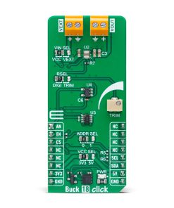
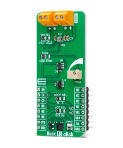
Buck 18 Click is based on the MAXM38643, an ultra-low-IQ (330nA) buck module from Analog Devices. This module efficiently steps down input voltages from 1.8V to 5.5V (supplied via the VEXT terminal) to output voltages between 0.7V and 3.3V on the VOUT terminal. Additionally, the output voltage is accessible through the analog AN pin on the mikroBUS™ socket. Users can manually adjust the output voltage using the onboard TRIM trimmer or digitally via the AD5171 digital potentiometer controlled through the I2C interface. The adjustment method is selected by positioning the RSEL jumper to either DIGI or TRIM. The AD5171 also allows setting its I2C address using the ADDR SEL jumper.

This module is designed for optimal performance, automatically switching between ultra-low-power mode (ULPM), low-power mode (LPM), and high-power mode (HPM) based on the load current, ensuring efficiency and a quick transient response. In ULPM, the module overregulates to enhance efficiency and allows the output capacitor to manage transient load currents up to 600mA. It is particularly well-suited for portable devices, wearables, hearables, ultra-low-power IoT applications, single Li+ and coin cell battery devices, and more.
Besides the I2C interface pins, the board also uses the EN pin for control, which functions as the device enable. Setting this pin to a HIGH logic level enables the buck module while setting it to LOW disables the part and puts it into Shutdown mode.
Buck 18 Click also offers versatile power sourcing options, allowing users to choose between internal and external supplies to best suit their application needs. This flexibility is achieved through the VIN SEL jumper, which enables users to select the VCC position for sourcing power internally via the mikroBUS™ power rails or the VEXT position to connect an external power supply. As mentioned, the external power supply can range from 1.8V to 5.5V, providing a broad voltage range for various project requirements.
This Click board™ can operate with either 3.3V or 5V logic voltage levels selected via the VCC SEL jumper. This way, both 3.3V and 5V capable MCUs can use the communication lines properly. Also, this Click board™ comes equipped with a library containing easy-to-use functions and an example code that can be used as a reference for further development.
Type
Buck
Applications
Ideal for portable devices, wearables, ultra-low-power IoT applications, and battery-powered systems
On-board modules
MAXM38643 – ultra-low-IQ nanoPower buck module from Analog Devices
Key Features
Voltage step-down, ultra-low power consumption, adjustable output voltage (via trimmer or digital potentiometer), load current up to 600mA, automatic power mode switching, I2C interface, selectable power sourcing (internal or external), and more
Interface
Analog,I2C
Feature
ClickID
Compatibility
mikroBUS™
Click board size
L (57.15 x 25.4 mm)
Input Voltage
3.3V or 5V,External
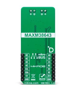
This table shows how the pinout on Buck 18 Click corresponds to the pinout on the mikroBUS™ socket (the latter shown in the two middle columns).
| Notes | Pin | Pin | Notes | ||||
|---|---|---|---|---|---|---|---|
| Analog Output | AN | 1 | AN | PWM | 16 | NC | |
| Device Enable | EN | 2 | RST | INT | 15 | NC | |
| ID COMM | CS | 3 | CS | RX | 14 | NC | |
| NC | 4 | SCK | TX | 13 | NC | ||
| NC | 5 | MISO | SCL | 12 | SCL | I2C Clock | |
| NC | 6 | MOSI | SDA | 11 | SDA | I2C Data | |
| Power Supply | 3.3V | 7 | 3.3V | 5V | 10 | 5V | Power Supply |
| Ground | GND | 8 | GND | GND | 9 | GND | Ground |
| Label | Name | Default | Description |
|---|---|---|---|
| LD1 | PWR | – | Power LED Indicator |
| JP1 | VCC SEL | Left | Power Voltage Level Selection 3V3/5V: Left position 3V3, Right position 5V |
| JP2 | VIN SEL | Left | MAXM38643 Power Supply Selection VCC/VEXT: Left position VCC, Right position VEXT |
| JP3 | RSEL | Left | Output Voltage Configuration Selection DIGI/TRIM: Left position DIGI, Right position TRIM |
| JP4 | ADDR SEL | Left | I2C Address Selection 0/1: Left position 0, Right position 1 |
| P1 | TRIM | – | Output Voltage / UVLO Trimmer |
| Description | Min | Typ | Max | Unit |
|---|---|---|---|---|
| Supply Voltage | 3.3 | – | 5 | V |
| External Power Supply | 1.8 | – | 5.5 | V |
| Output Voltage | 0.7 | – | 3.3 | V |
| Load Current | – | – | 600 | mA |
We provide a library for the Buck 18 Click as well as a demo application (example), developed using MIKROE compilers. The demo can run on all the main MIKROE development boards.
Package can be downloaded/installed directly from NECTO Studio Package Manager (recommended), downloaded from our LibStock™ or found on MIKROE github account.
Library Description
This library contains API for Buck 18 Click driver.
Key functions
buck18_set_vout This function sets the voltage output level.
buck18_read_voltage This function reads raw ADC value and converts it to proportional voltage level.
buck18_enable This function turns on the power switch and enables the buck mode.
Example Description
This example demonstrates the use of the Buck 18 Click board™ by changing the output voltage.
void application_task ( void )
 {
     for ( buck18_vout_t vout = BUCK18_VOUT_3V3; vout <= BUCK18_VOUT_0V9; vout++ )
     {
         if ( BUCK18_OK == buck18_set_vout( &buck18, vout ) )
         {
             float voltage = 0;
             if ( BUCK18_OK == buck18_read_voltage( &buck18, &voltage ) )
             {
                 log_printf( &logger, " Voltage : %.3f[V]rnn", voltage );
                 Delay_ms( 5000 );
             }
         }
     }
 }
The full application code, and ready to use projects can be installed directly from NECTO Studio Package Manager (recommended), downloaded from our LibStock™ or found on MIKROE github account.
Other MIKROE Libraries used in the example:
Additional notes and informations
Depending on the development board you are using, you may need USB UART click, USB UART 2 Click or RS232 Click to connect to your PC, for development systems with no UART to USB interface available on the board. UART terminal is available in all MIKROE compilers.
This Click board™ is supported with mikroSDK – MIKROE Software Development Kit. To ensure proper operation of mikroSDK compliant Click board™ demo applications, mikroSDK should be downloaded from the LibStock and installed for the compiler you are using.
For more information about mikroSDK, visit the official page.
| Weight | 20 g |
|---|---|
| Brand | MikroElektronika |