BT122-A Click
R1,250.00 ex. VAT
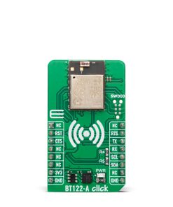
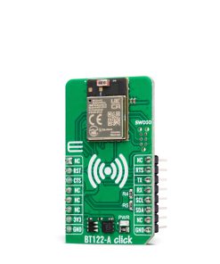
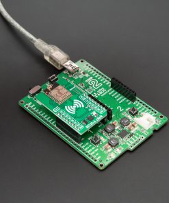
BT122-A Click is a compact add-on board designed for Bluetooth connectivity in low-energy and Classic communication applications. This board features the BT122-A, a dual-mode Bluetooth BR/EDR and BLE v4.2 module from Silicon Labs, with robust performance and flexibility. The BT122-A integrates a high-power Bluetooth radio with +11dBm transmit power and -95dBm receive sensitivity, a built-in antenna, and a low-power 32-bit ARM Cortex-M4 MCU for advanced processing capabilities. It communicates with the host MCU via UART and supports standalone operation with embedded applications using BGScript™. Ideal for cable replacement, health and fitness monitoring, industrial automation, and smart home systems, BT122-A Click ensures reliable Bluetooth connectivity across diverse use cases.
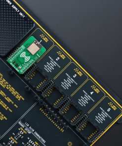
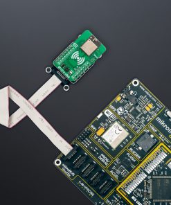
BT122-A Click is fully compatible with the mikroBUS™ socket and can be used on any host system supporting the mikroBUS™ standard. It comes with the mikroSDK open-source libraries, offering unparalleled flexibility for evaluation and customization. What sets this Click board™ apart is the groundbreaking ClickID feature, enabling your host system to seamlessly and automatically detect and identify this add-on board.
Stock: Lead-time applicable.
| 5+ | R1,187.50 |
| 10+ | R1,125.00 |
| 15+ | R1,062.50 |
| 20+ | R1,022.50 |
How does it work?
BT122-A Click is based on the BT122-A, a dual-mode Bluetooth BR/EDR and BLE v4.2 module from Silicon Labs. This module is specifically designed for applications that demand Bluetooth Low Energy and Classic connectivity, offering communication with legacy devices supporting Bluetooth SPP or Apple® iAP2 profiles and modern devices that use Bluetooth Low Energy protocols. The BT122-A integrates a robust Bluetooth radio with up to +11dBm transmit power and -95dBm receive sensitivity, ensuring reliable communication over extended ranges. Additionally, the module features a built-in antenna and is powered by a low-power 32-bit ARM Cortex-M4 microcontroller, which, in combination with Silicon Labs’ Dual Mode stack software, provides exceptional processing efficiency and advanced connectivity capabilities.

The BT122-A is engineered to operate either as a standalone modem controlled by an external host MCU or as an independent application processor. For standalone operation, developers can use the integrated ARM Cortex-M4 MCU, enabling the embedding of applications using the Silicon Labs BGScript™ scripting language. This flexibility makes the module suitable for a wide range of use cases. Whether for cable replacement, HID devices, or advanced applications like health and fitness monitoring, industrial automation, M2M connectivity, or home automation gateways, the BT122-A Click delivers high performance and adaptability to meet diverse application requirements.
This Click board™ establishes communication between the BT122-A module and the host MCU through a UART interface, using standard UART RX and TX pins and hardware flow control via CTS and RTS pins. The default communication speed is set at 115200bps, ensuring efficient data exchange. The host MCU configures communication and other features using high-level AT commands, making it easy to manage without requiring in-depth knowledge of Bluetooth protocol. Additionally, the board includes an I2C interface with a maximum clock speed of 1MHz.
In addition to the interface pins, the board features a reset (RST) pin for hard-resetting the module when necessary and SWD pads designed for use with MIKROE’s 6-pin Needle Cable, providing an optional flash and debug SWD (Serial Wire Debug) interface functionality.
This Click board™ can be operated only with a 3.3V logic voltage level. The board must perform appropriate logic voltage level conversion before using MCUs with different logic levels. It also comes equipped with a library containing functions and example code that can be used as a reference for further development.
Specifications
Type
BT/BLE
Applications
Ideal for cable replacement, health and fitness monitoring, industrial automation, and smart home systems
On-board modules
BT122-A – dual-mode Bluetooth BR/EDR and BLE v4.2 module from Silicon Labs
Key Features
Low-power 32-bit ARM Cortex-M4 microcontroller with embedded application support using BGScript™, +11dBm transmit power and -95dBm receive sensitivity, built-in antenna, UART and I2C interfaces, reset and debug support, and more
Interface
I2C,UART
Feature
ClickID
Compatibility
mikroBUS™
Click board size
M (42.9 x 25.4 mm)
Input Voltage
3.3V
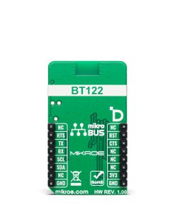
Pinout diagram
This table shows how the pinout on BT122-A Click corresponds to the pinout on the mikroBUS™ socket (the latter shown in the two middle columns).
| Notes | Pin | Pin | Notes | ||||
|---|---|---|---|---|---|---|---|
| NC | 1 | AN | PWM | 16 | NC | ||
| ID SEL | RST | 2 | RST | INT | 15 | RTS | UART RTS |
| UART CTS / ID COMM | CTS | 3 | CS | RX | 14 | TX | UART TX |
| NC | 4 | SCK | TX | 13 | RX | UART RX | |
| NC | 5 | MISO | SCL | 12 | SCL | I2C Clock | |
| NC | 6 | MOSI | SDA | 11 | SDA | I2C Data | |
| Power Supply | 3.3V | 7 | 3.3V | 5V | 10 | NC | |
| Ground | GND | 8 | GND | GND | 9 | GND | Ground |
Onboard settings and indicators
| Label | Name | Default | Description |
|---|---|---|---|
| LD1 | PWR | – | Power LED Indicator |
BT122-A Click electrical specifications
| Description | Min | Typ | Max | Unit |
|---|---|---|---|---|
| Supply Voltage | – | 3.3 | – | V |
| Frequency Range | 2402 | – | 2480 | MHz |
| TX Power | – | +11 | – | dBm |
| RX Sensitivity | – | -95 | – | dBm |
Software Support
BT122-A Click demo application is developed using the NECTO Studio, ensuring compatibility with mikroSDK‘s open-source libraries and tools. Designed for plug-and-play implementation and testing, the demo is fully compatible with all development, starter, and mikromedia boards featuring a mikroBUS™ socket.
Example Description
This example demonstrates the use of BT122-A Click board by processing data from a connected BT device.
Key Functions
bt122a_cfg_setupConfig Object Initialization function.bt122a_initInitialization function.bt122a_set_local_nameThis function sets the local name of the device.bt122a_send_packageThis function sends a data package to the Click board.bt122a_read_packageThis function waits for the command or event type of message to arrive and then reads the complete message and stores it to the pkg structure.
Application Init
Initializes the driver and configures the Click board.
Application Task
Handles most of the events required for this example, the packages of events not supported in this example will just be displayed on the USB UART. The event handler will display all messages received from the remote device on the USB UART and echo the same message to the connected device.
Application Output
This Click board can be interfaced and monitored in two ways:
- Application Output – Use the “Application Output” window in Debug mode for real-time data monitoring. Set it up properly by following this tutorial.
- UART Terminal – Monitor data via the UART Terminal using a USB to UART converter. For detailed instructions, check out this tutorial.
Additional Notes and Information
The complete application code and a ready-to-use project are available through the NECTO Studio Package Manager for direct installation in the NECTO Studio. The application code can also be found on the MIKROE GitHub account.
Resources
Downloads
| Weight | 18 g |
|---|---|
| Brand | MikroElektronika |