How does it work?
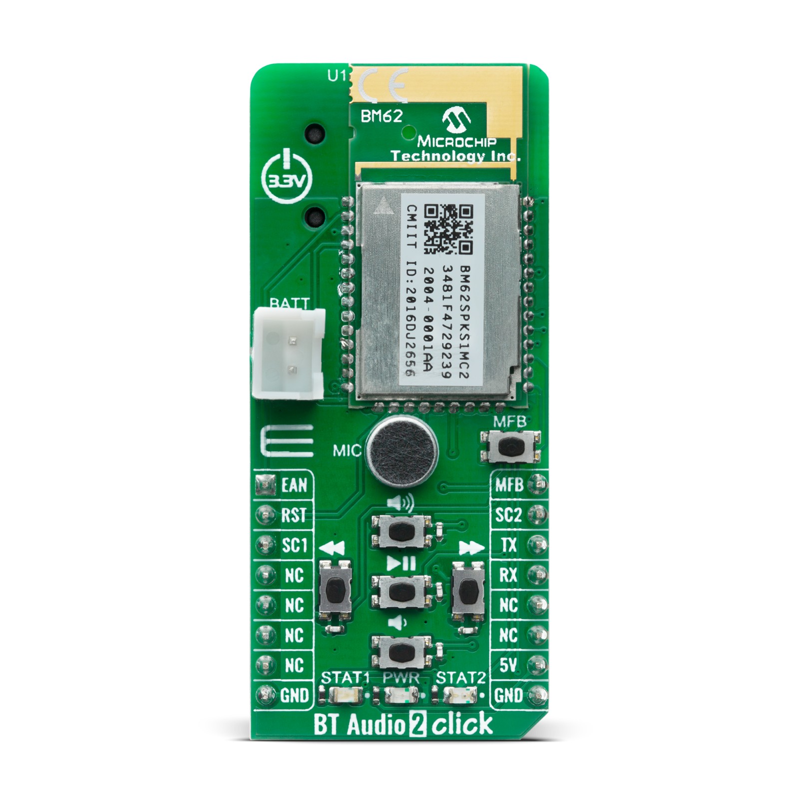
BT Audio 2 Click includes advanced audio features, such as multi-band dynamic range control, parametric multi-band equalizer, audio widening and virtual bass are inbuilt. The audio effect algorithms improve the user’s audio listening experience in terms of better audio quality after audio signal processing.
The input and output audios have different stages and each stage can be programmed to vary the gain response characteristics. A Digital Signal Processor (DSP) is used to perform speech and audio processing. The advanced speech features, such as acoustic echo cancellation and noise reduction are inbuilt. To reduce nonlinear distortion and to help echo cancellation, an outgoing signal level to the speaker is monitored and adjusted to avoid saturation of speaker output or microphone input.
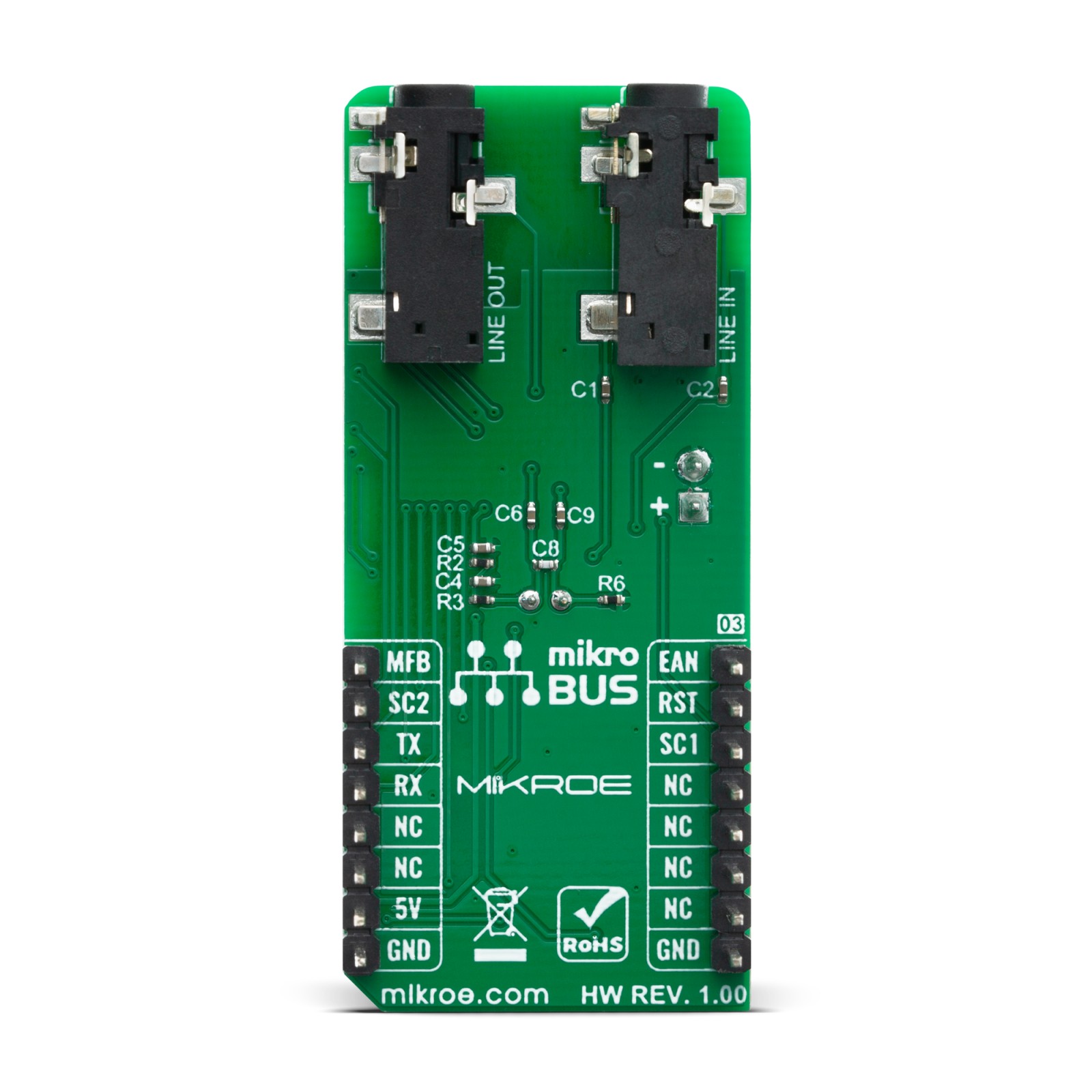
BT Audio 2 Click supports one analog (line-in) signal from the external audio source. The analog (line-in) signal can be processed by the DSP to generate different sound effects (multi-band dynamic range compression and audio widening), which can be configured by using the DSP tool. Also, module has an AFH function to avoid RF interference. It has an algorithm to check the nearby interference and to choose clear channel for transceiver Bluetooth signal.
The on-chip Power Management Unit (PMU) has two main features: lithium-ion and lithium-polymer battery charger, and voltage regulator. A power switch is used to switch over the power source between the battery and an adapter. Also, the PMU provides current to drive two LEDs. The LED and button settings can be configured.
This Click Board™ uses the UART communication interface and is designed to be operated only with a 3.3V logic level. A proper logic voltage level conversion should be performed before the Click board™ is used with MCUs with different logic levels.
Specifications
Type
BT/BLE
Applications
Portable speaker, Multiple speakers, Headset and many more
On-board modules
BM62SPKS1MC2-0001AA
Key Features
Qualified for Bluetooth v5.0 specification, high resolution up to 24-bit, 96 kHz audio data format, Bluetooth Low Energy data rate up to 1Mbits/s, connection of two hosts with HFP/A2DP profiles simultaneously
Interface
GPIO,UART
Feature
No ClickID
Compatibility
mikroBUS™
Click board size
L (57.15 x 25.4 mm)
Input Voltage
3.3V
Pinout diagram
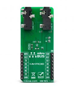
This table shows how the pinout on BT Audio 2 Click corresponds to the pinout on the mikroBUS™ socket (the latter shown in the two middle columns).
Onboard settings and indicators
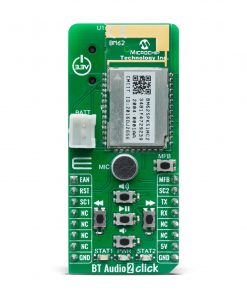
Label | Name | Default | Description |
---|---|---|---|
PWR | LD1 | – | Power LED Indicator |
STAT1 | LD2 | – | Configurable indication LED 1 |
STAT2 | LD3 | – | Configurable indication LED 2 |
MFB | – | – | Multi-Function button |
REV | – | – | Reverse command button |
VOL_DN | – | – | Volume-down command button |
FWD | – | – | Forward command button |
VOL_UP | – | – | Volume-up command button |
PLAY/PAUSE | – | – | Play/Pause command button |
Software Support
We provide a library for the BT Audio 2 Click on our LibStock page, as well as a demo application (example), developed using MikroElektronika compilers. The demo can run on all the main MikroElektronika development boards.
Library Description
This library allows to establish a communication with the BT Audio 2 Click (BM62 module). On this way we can perform a full control of the module, such as playing songs control, EQ control, Bluetooth connection control, status reading, etc. The response reading and checking are also supported by this library. For more details, please, check full documentation.
Key functions:
void btaudio2_response_handler_set( void ( *handler )( uint8_t*, uint16_t*, uint16_t* ) );
– This function sets handler on the function that should be performed.btaudio2_err_t btaudio2_make_call( uint8_t data_base, unsigned char *phone_num );
– This command is used to trigger HF action for making an outgoing call.btaudio2_err_t btaudio2_song_ctrl( uint8_t ctrl_byte );
– This command is used to perform the song control, such as the song volume, song selection, etc.
Examples description
The application is composed of three sections :
- System Initialization – Initializes all necessary peripherals and pins.
- Application Initialization – Initializes UART interface and performs the BTM device enabling, reset and mode configuration. Also sets a default callback function for the response checking.
- Application Task – (code snippet) – Allows user to execute a full music control, such as volume control, song control, EQ control, BT power control. Note: By using driver functions user can perform the all other module functionality. Using the selected UART terminal user can check every command and event response.
void application_task( ) { uint8_t rx_dat = UART_Rdy_Ptr( ); if ( rx_dat != RX_UART_NOT_READY ) { rx_dat = UART_Rd_Ptr( ); switch ( rx_dat ) { case 'o' : { btaudio2_power_on_off( ); break; } case 's' : { btaudio2_play_ctrl( BTAUDIO2_STOP ); mikrobus_logWrite( ">> Command: ", _LOG_TEXT ); log_response( ); break; } case 'p' : { btaudio2_play_ctrl( BTAUDIO2_PLAY_PAUSE ); mikrobus_logWrite( ">> Command: ", _LOG_TEXT ); log_response( ); break; } case '4' : { btaudio2_song_ctrl( BTAUDIO2_PREV_SONG ); mikrobus_logWrite( ">> Command: ", _LOG_TEXT ); log_response( ); break; } case '6' : { btaudio2_song_ctrl( BTAUDIO2_NEXT_SONG ); mikrobus_logWrite( ">> Command: ", _LOG_TEXT ); log_response( ); break; } case '+' : { btaudio2_song_ctrl( BTAUDIO2_VOLUME_UP ); mikrobus_logWrite( ">> Command: ", _LOG_TEXT ); log_response( ); break; } case '-' : { btaudio2_song_ctrl( BTAUDIO2_VOLUME_DOWN ); mikrobus_logWrite( ">> Command: ", _LOG_TEXT ); log_response( ); break; } case 'e' : { set_eq_mode( ); mikrobus_logWrite( ">> Command: ", _LOG_TEXT ); log_response( ); break; } default : { break; } } } check_response_ready( ); }
Additional Functions :
- collect_response – Collects a response sequence to the response buffer.
- log_response – Sends the response to the determined uart terminal.
- check_response_ready – Checks response ready flag and if the response is ready then calls the log_response function.
- set_eq_mode – Performs the changing of 10 differents EQ modes of the BTM device. The uart rx interrupt will catch every byte which was sent to the uart rx buffer on the host mcu.
The full application code, and ready to use projects can be found on our LibStock page.
Other mikroE Libraries used in the example:
- Conversions
- C_String
- UART
Additional notes and informations
Depending on the development board you are using, you may need USB UART click, USB UART 2 click or RS232 click to connect to your PC, for development systems with no UART to USB interface available on the board. The terminal available in all MikroElektronika compilers, or any other terminal application of your choice, can be used to read the message.
mikroSDK
This Click board™ is supported with mikroSDK – MikroElektronika Software Development Kit. To ensure proper operation of mikroSDK compliant Click board™ demo applications, mikroSDK should be downloaded from the LibStock and installed for the compiler you are using.
For more information about mikroSDK, visit the official page.