Brushless 33 Click
R470.00 ex. VAT
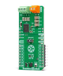
Brushless 33 Click is a compact add-on board designed for precise BLDC motor control. This board features the MCF8316A, a sensorless Field Oriented Control (FOC) integrated FET motor driver from Texas Instruments. This Click board™ supports 12V to 24V BLDC or PMSM motors with up to 8A peak current, featuring a code-free sensorless FOC algorithm for smooth and quiet motor operation. Its integrated protections, non-volatile EEPROM for configuration storage, and versatile control options via PWM, analog input, or I2C interface ensure reliable and flexible operation. Brushless 33 Click is ideal for residential and automotive fans, air purifiers, blowers, and medical CPAP devices.
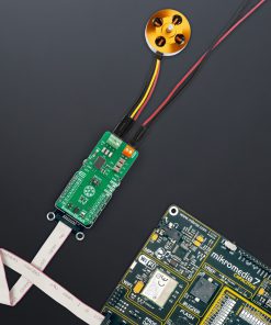
Brushless 33 Click is fully compatible with the mikroBUS™ socket and can be used on any host system supporting the mikroBUS™ standard. It comes with the mikroSDK open-source libraries, offering unparalleled flexibility for evaluation and customization. What sets this Click board™ apart is the groundbreaking ClickID feature, enabling your host system to seamlessly and automatically detect and identify this add-on board.
Stock: Lead-time applicable.
| 5+ | R446.50 |
| 10+ | R423.00 |
| 15+ | R399.50 |
| 20+ | R384.46 |
How does it work?
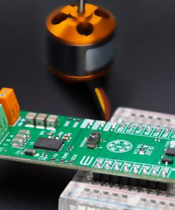
Brushless 33 Click is based on the MCF8316A, a sensorless Field Oriented Control (FOC) integrated FET brushless DC (BLDC) driver from Texas Instruments, designed for BLDC motor control applications. This three-phase motor driver incorporates a code-free sensorless FOC algorithm, making it an ideal solution for controlling speed-regulated 12V to 24V BLDC or Permanent Magnet Synchronous Motors (PMSM) with a peak current of up to 8A. The MCF8316A integrates three half-bridges with an exceptionally low RDS(ON) value of 95mΩ (combined high-side and low-side), ensuring minimal energy loss and maximum efficiency during operation. Furthermore, the device allows for standalone functionality by storing algorithm configurations in its non-volatile EEPROM, enabling consistent and reliable motor control without additional external coding or adjustments once configured. Based on its broad range of features, the Brushless 33 Click is well-suited for numerous applications, including residential and living fans, air purifiers, humidifier fans, automotive fans, blowers, and medical CPAP blowers.

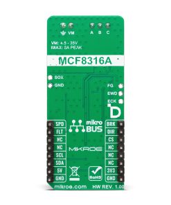
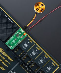
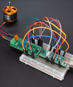
The MCF8316A includes protection features to safeguard the device, motor, and overall system from potential faults. These integrated protections ensure robust performance and long-term reliability across diverse operating conditions. With its sensorless FOC algorithm, the MCF8316A offers smooth motor speed control, even in applications requiring quiet and efficient operation. The Brushless 33 Click operates from an external power supply connected to the VM terminal, with a recommended operating range of 4.5V to 35V. Its output terminals, A, B, and C, can deliver a peak drive current of up to 8A, ensuring operation for spinning a three-phase sensorless Brushless DC (BLDC) motor. The A2212/13T 1000KV BLDC motor is one of our recommendations for optimal performance. In addition to the motor connection terminals, the board includes three dedicated hooks that serve as test points for the three phases of the BLDC motor, allowing for convenient monitoring and diagnostics during operation.
This Click board™ is controlled by the host MCU using several pins and their corresponding logic states. The SPD pin allows for motor speed control through PWM by varying the duty cycle of the input signal, while speed can also be adjusted using frequency or an analog input on the SPD pin or configured via the I2C configuration register. The BRK pin brakes the motor when set to a HIGH logic state and enables normal operation when set to LOW. The DIR pin determines the direction of motor rotation, with a LOW state resulting in an A-C-B driving sequence and a HIGH state corresponding to an A-B-C sequence. Additionally, the FLT pin signals when a fault condition occurs in the MCF8316A. To provide visual feedback, several LED indicators reflect the state of key signals: a green LED for SPEED, a yellow LED for BRAKE, and a red LED for FAULT, ensuring quick and intuitive monitoring of the system’s operation.
The MCF8316A includes the mentioned I2C interface, which allows an external host MCU to configure its various settings and access fault diagnostic information. The board also features a DRVOFF switch that enables or disables the internal gate drivers; in position 0, the MCF8316A is disabled, while in position 1, it is enabled for operation. Additionally, the board includes unpopulated pins offering extended functionality.
The FG pin outputs pulses proportional to the motor’s speed, providing a convenient way to monitor rotational speed. The SOX pin outputs the signal from one of the current sense amplifiers, offering precise current measurement capabilities. The EWD and ECK pins are optional inputs for external oscillator and watchdog signals. The ECK pin can provide an external clock reference, while the EWD pin can accept an external watchdog signal, enhancing system reliability and enabling advanced timing control.
This Click board™ can operate with either 3.3V or 5V logic voltage levels selected via the VCC SEL jumper. This way, both 3.3V and 5V capable MCUs can use the communication lines properly. Also, this Click board™ comes equipped with a library containing easy-to-use functions and an example code that can be used as a reference for further development.
Specifications
Type
Brushless
Applications
Ideal for residential and automotive fans, air purifiers, blowers, and medical CPAP devices
On-board modules
MCF8316A – sensorless Field Oriented Control (FOC) integrated FET motor driver from Texas Instruments
Key Features
Supports three-phase BLDC or PMSM motors with up to 8A peak current, speed control via PWM, analog input, frequency input, or I2C configuration, configurable driving sequence, brake functionality, fault detection, speed feedback, current sensing, integrated protection, and more
Interface
GPIO,I2C,PWM
Feature
ClickID
Compatibility
mikroBUS™
Click board size
L (57.15 x 25.4 mm)
Input Voltage
3.3V or 5V,External
Pinout diagram
This table shows how the pinout on Brushless 33 Click corresponds to the pinout on the mikroBUS™ socket (the latter shown in the two middle columns).
| Notes | Pin | Pin | Notes | ||||
|---|---|---|---|---|---|---|---|
| Motor Brake Control | BRK | 1 | AN | PWM | 16 | SPD | Motor Speed Control |
| Motor Direction Control | DIR | 2 | RST | INT | 15 | FLT | Fault Interrupt |
| ID COMM | CS | 3 | CS | RX | 14 | NC | |
| NC | 4 | SCK | TX | 13 | NC | ||
| NC | 5 | MISO | SCL | 12 | SCL | I2C Clock | |
| NC | 6 | MOSI | SDA | 11 | SDA | I2C Data | |
| Power Supply | 3.3V | 7 | 3.3V | 5V | 10 | 5V | Power Supply |
| Ground | GND | 8 | GND | GND | 9 | GND | Ground |
Onboard settings and indicators
| Label | Name | Default | Description |
|---|---|---|---|
| LD1 | PWR | – | Power LED Indicator |
| LD2 | SPEED | – | Motor Speed LED Indicator |
| LD3 | BRAKE | – | Motor Brake LED Indicator |
| LD4 | FAULT | – | Fault LED Indicator |
| JP1 | VCC SEL | Left | Power Voltage Level Selection 3V3/5V: Left position 3V3, Right position 5V |
| SW1 | DRVOFF | Right | Driver Enable Switch 0/1: Left position 0, Right position 1 |
Brushless 33 Click electrical specifications
| Description | Min | Typ | Max | Unit |
|---|---|---|---|---|
| Supply Voltage | 3.3 | – | 5 | V |
| External Power Supply | 4.5 | – | 35 | V |
| Peak Output Current | – | – | 8 | A |
Software Support
Brushless 33 Click demo application is developed using the NECTO Studio, ensuring compatibility with mikroSDK‘s open-source libraries and tools. Designed for plug-and-play implementation and testing, the demo is fully compatible with all development, starter, and mikromedia boards featuring a mikroBUS™ socket.
Example Description
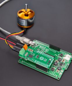
This example demonstrates the control of an A2212/13T 1000KV motor using the Brushless 33 Click board. The example showcases basic motor operations, including speed adjustments, direction switching, and fault handling. The motor speed is controlled by varying the PWM duty cycle.
Key Functions
brushless33_cfg_setupConfig Object Initialization function.brushless33_initInitialization function.brushless33_default_cfgClick Default Configuration function.brushless33_set_duty_cycleThis function sets the PWM duty cycle in percentages ( Range[ 0..1 ] ).brushless33_switch_directionThis function switches the direction of motor rotation by toggling the DIR pin logic state.brushless33_get_fault_pinThis function returns the fault indication pin logic state.
Application Init
Initializes the logger and configures the Click board.
Application Task
Adjusts the motor’s duty cycle to control its speed, alternating between increasing and decreasing duty values. Fault conditions are checked and resolved to maintain stable operation. Additional motor controls, such as switching direction and braking, are triggered based on the duty cycle limits. Each step will be logged on the USB UART where you can track the program flow.
Application Output
This Click board can be interfaced and monitored in two ways:
- Application Output – Use the “Application Output” window in Debug mode for real-time data monitoring. Set it up properly by following this tutorial.
- UART Terminal – Monitor data via the UART Terminal using a USB to UART converter. For detailed instructions, check out this tutorial.
Additional Notes and Information
The complete application code and a ready-to-use project are available through the NECTO Studio Package Manager for direct installation in the NECTO Studio. The application code can also be found on the MIKROE GitHub account.
Resources
Downloads
| Weight | 20 g |
|---|---|
| Brand | MikroElektronika |