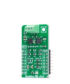
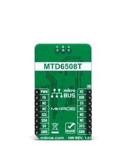
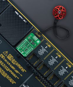
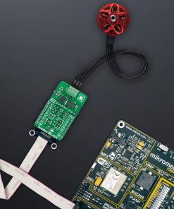
Brushless 22 Click
R195.00 ex. VAT
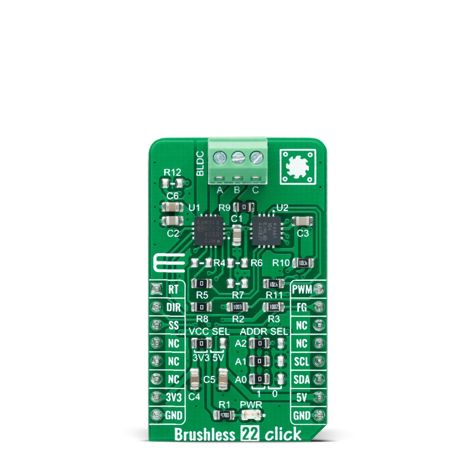
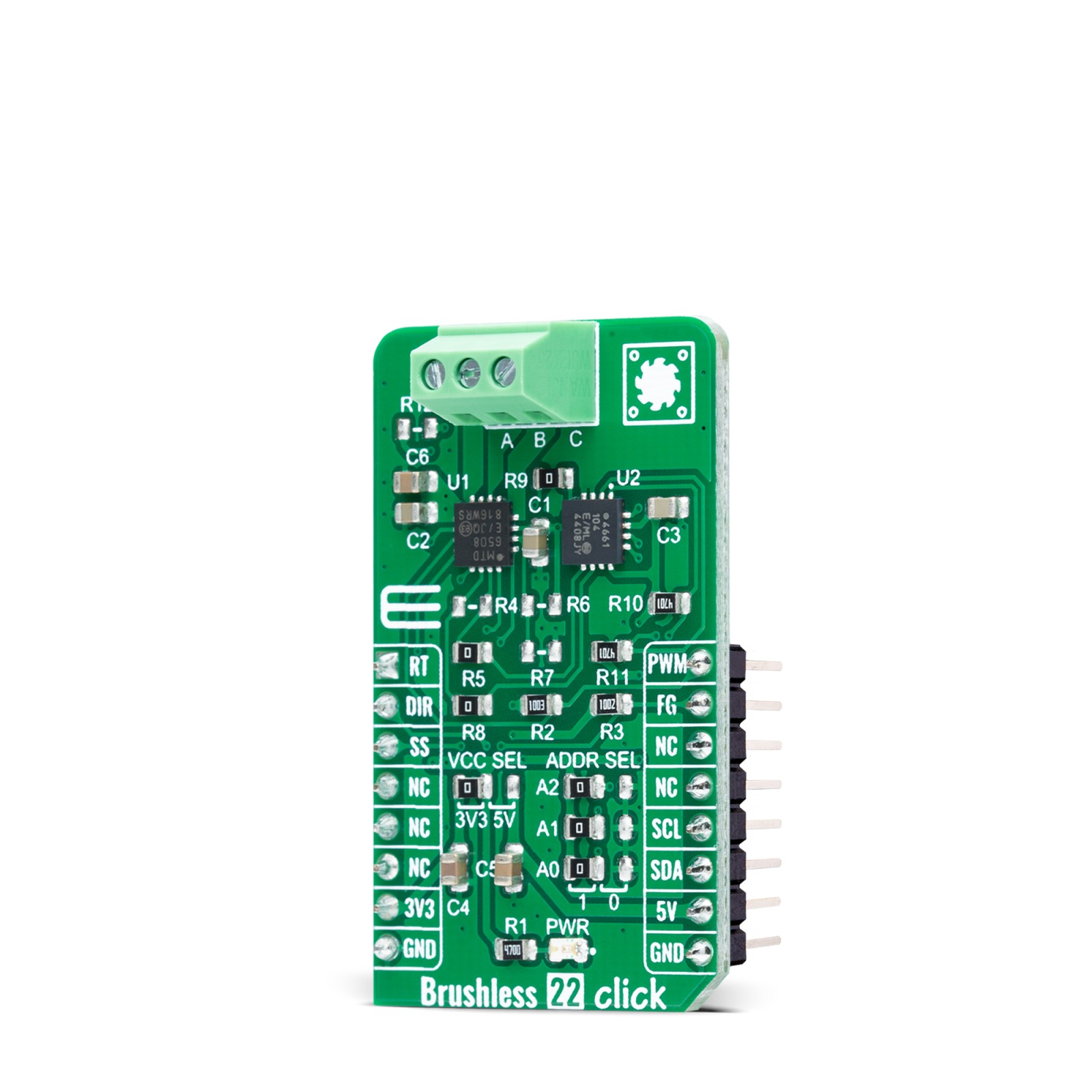
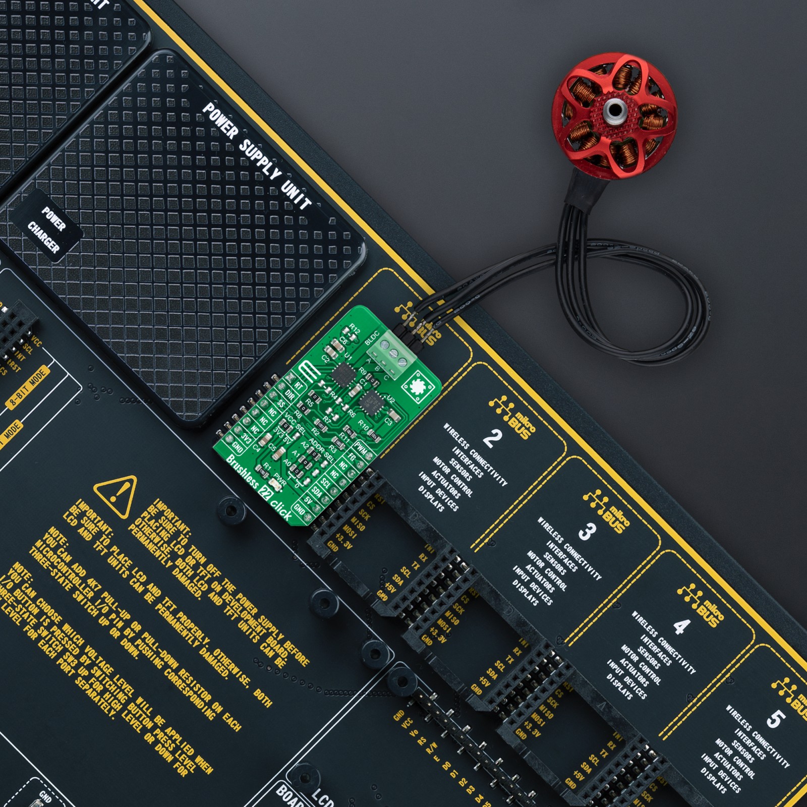
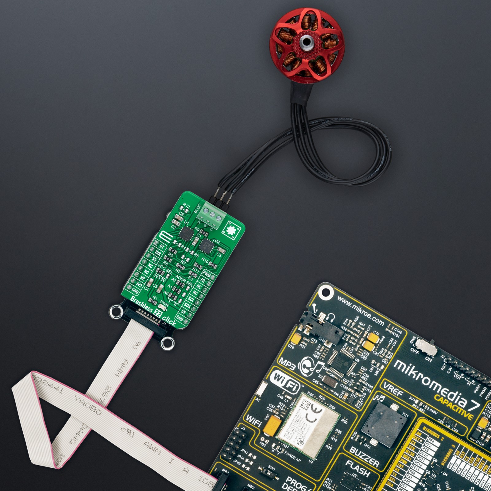
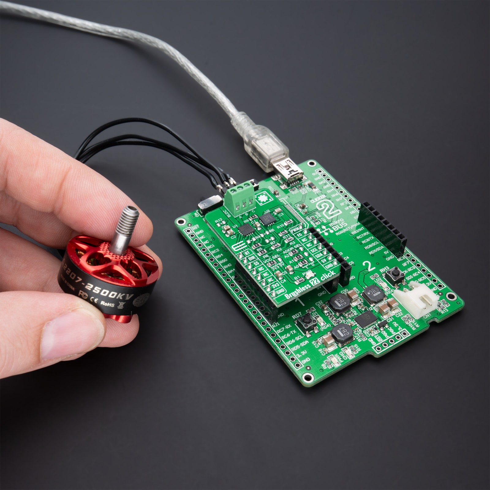
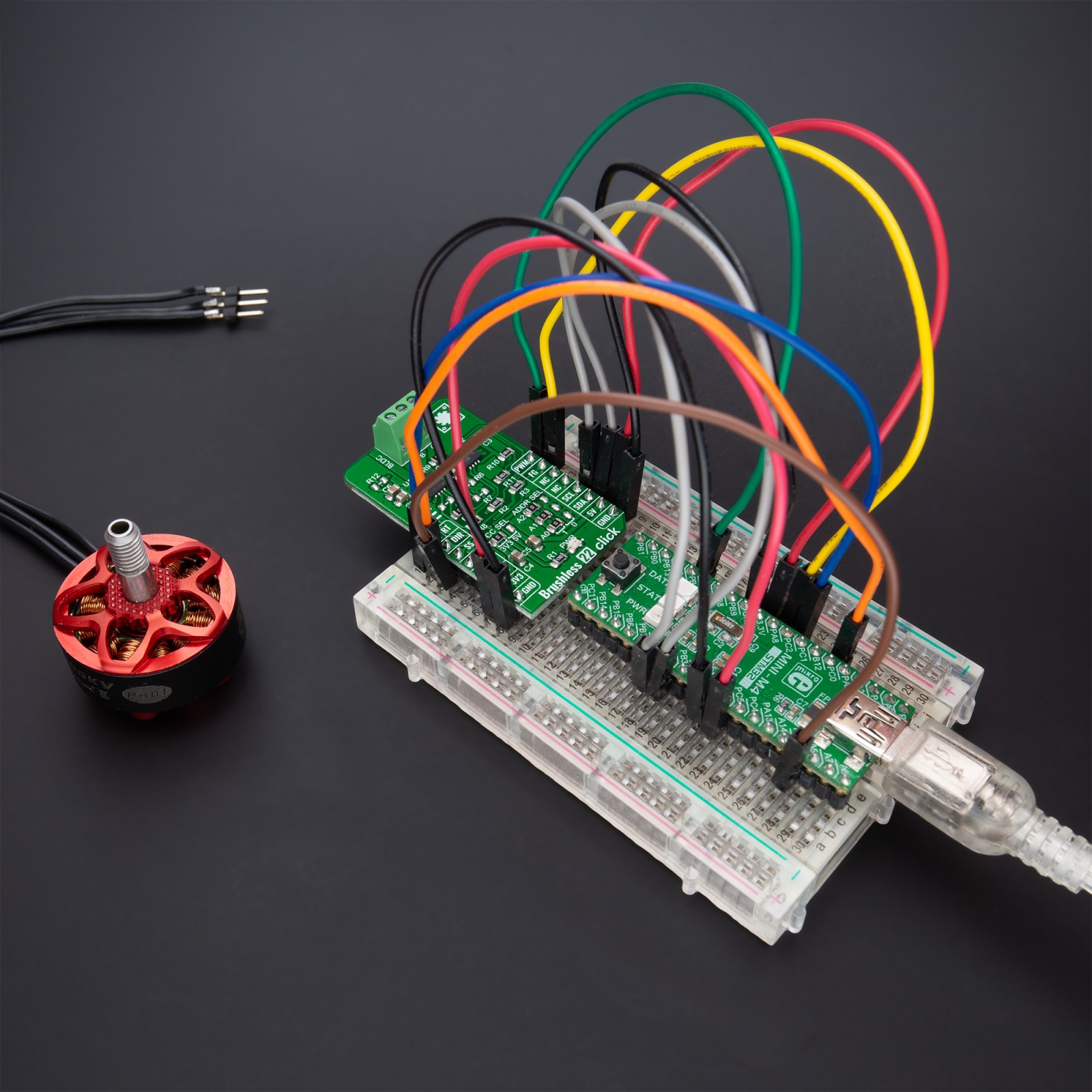
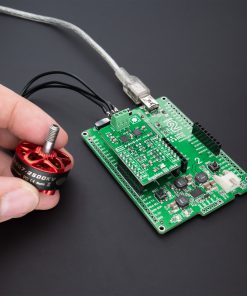
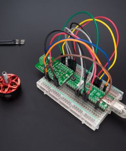
Brushless 22 Click is a compact add-on board suitable for controlling brushless DC (BLDC) motors with any MCU. This board features the MTD6508, a 3-phase full-wave sensorless driver for BLDC motors from Microchip Technology. It features 180° sinusoidal drive, high torque output, and silent drive, rated for an operating voltage range including both mikroBUS™ power rails, and comes with speed control achieved through pulse-width modulation (PWM). Besides, it features several diagnostic circuits and drive-control functions such as motor lock protection, overcurrent limitation, and thermal shutdown protection. This Click board™ makes the perfect solution for home appliances and industrial equipment, such as cooling fans.
Brushless 22 Click is supported by a mikroSDK compliant library, which includes functions that simplify software development. This Click board™ comes as a fully tested product, ready to be used on a system equipped with the mikroBUS™ socket.
Stock: Lead-time applicable.
| 5+ | R185.25 |
| 10+ | R175.50 |
| 15+ | R165.75 |
| 20+ | R159.51 |
How does it work?
Brushless 22 Click as its foundation uses the MTD6508, a 3-phase full-wave sensorless driver for brushless DC motors from Microchip Technology. It features a 180° sinusoidal drive, high torque output, and silent drive. High efficiency and low power consumption are achieved due to CMOS transistors and a synchronous rectification drive type. With adaptive features and parameters, the MTD6508 is intended to cover a broad range of motor characteristics, making this Click board™ extremely cost-efficient in fan applications that require low acoustic noise, low mechanical vibration, and are highly efficient.

This device provides start-up output slew rate and PWM duty cycle control that permit designers to balance acoustic performance and reliability. The rotational speed of the motor is controlled through the mikroBUS™ PWM signal. When the PWM signal is high, the motor rotates at full speed, and when the PWM signal is low, the MTD6508 outputs are set to a high impedance state, and the motor is stopped. The sinusoidal start-up open-loop phase current amplitude is controlled via SS pin, routed on the CS pin of the mikroBUS™ socket, which according to its logic state, chooses whether it is defined by the PWM input duty cycle or fixed at 100%. The output PWM slew rate can be adjusted with the R4 resistor during Start-Up, which is not populated in a default configuration to reduce motor vibration.
By default configuration, the output PWM slew rate can be set via the MCP4661 digital potentiometer from Microchip Technology, which establishes communication with the MCU via I2C serial communication. The MCP4661 also allows the choice of the least significant bit (LSB) of its I2C slave address by positioning SMD jumpers labeled as ADDR SEL to an appropriate position marked as 0 and 1. Once the Start-Up open loop is finished, the MTD6508 will automatically switch to a fixed slew rate. Choosing MCP4661 and not R4 for setting output PWM slew rate, unpopulate R4 resistor, and leave populated R5 and R8.
In addition to the output PWM slew rate and its setting method, the user is also given the option of setting the electromechanical coupling coefficient of the motor (also referred to as “motor constant” or “BEMF constant”) via R9 resistor, which is populated in default configuration or by R6 and R7 voltage divider. The MTD6508 defines the BEMF coefficient as the peak value of the phase-to-phase BEMF voltage normalized to the electrical speed of the motor. Choosing MCP4661 and not voltage divider for setting BEMF constant, unpopulate R9 resistor and leave populated R6 and R7.
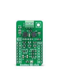
Alongside I2C communication, several GPIO pins connected to the mikroBUS™ socket pins are also used to forward the information to the MCU. The DIR pin, routed on the RST pin of the mikroBUS™ socket, is used to select the direction of motor rotation (clockwise/counterclockwise). The RT pin, routed on the AN pin of the mikroBUS™ socket, adjusts the phase regulation parameters to allow more stability in applications using 3-Phase BLDC motors attached to a light load, while the FG pin routed on the INT pin serves as a rotation speed indicator, gives information about the speed and phase of the motor. With R12 populated, the rotor speed rotation per minute (RPM) has to be multiplied by three because the FG signal frequency will be divided by three.
This Click board™ can operate with both 3.3V and 5V logic voltage levels selected via the VCC SEL jumper. This way, it is allowed for both 3.3V and 5V capable MCUs to use the communication lines properly. However, the Click board™ comes equipped with a library containing easy-to-use functions and an example code that can be used, as a reference, for further development.
Specifications
Type
Brushless
Applications
Can be used for home appliances and industrial equipment, such as cooling fans
On-board modules
MTD6508 – 3-phase full-wave sensorless driver for brushless DC motors from Microchip Technology
Key Features
180° sinusoidal drive for high efficiency and low acoustic noise, position sensorless BLDC driver, motor constant setting, speed control, PWM slew rate control, protection features, and more
Interface
GPIO,I2C,PWM
Feature
No ClickID
Compatibility
mikroBUS™
Click board size
M (42.9 x 25.4 mm)
Input Voltage
3.3V or 5V
Pinout diagram
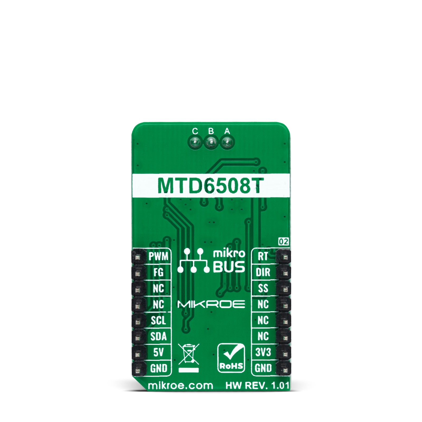
This table shows how the pinout on Brushless 22 Click corresponds to the pinout on the mikroBUS™ socket (the latter shown in the two middle columns).
Onboard settings and indicators
| Label | Name | Default | Description |
|---|---|---|---|
| LD1 | PWR | – | Power LED Indicator |
| JP1 | VCC SEL | Left | Logic Level Voltage Selection 3V3/5V: Left position 3V3, Right position 5V |
| JP2-JP4 | ADDR SEL | Left | I2C Address Selection 1/0: Left position 1, Right position 0 |
| R4 | R4 | Unpopulated | Output PWM Slew Rate Control via Resistor |
| R5/R8 | R5/R8 | Populated | Output PWM Slew Rate Control via MCP4661 |
| R9 | R9 | Populated | Motor Constant Selection via MCP4661 |
| R6/R7 | R6/R7 | Unpopulated | Motor Constant Selection via Resistors |
| R12 | R12 | Unpopulated | FG Frequency Divider Selection Jumper |
Brushless 22 Click electrical specifications
| Description | Min | Typ | Max | Unit |
|---|---|---|---|---|
| Supply Voltage | 3.3 | – | 5 | V |
| Maximum Output Current | – | – | 1 | A |
| Operating Frequency | 1 | – | 100 | kHz |
| Operating Temperature Range | -40 | +25 | +120 | °C |
Software Support
We provide a library for the Brushless 22 Click as well as a demo application (example), developed using MikroElektronika compilers. The demo can run on all the main MikroElektronika development boards.
Package can be downloaded/installed directly from NECTO Studio Package Manager(recommended way), downloaded from our LibStock™ or found on Mikroe github account.
Library Description
This library contains API for Brushless 22 Click driver.
Key functions
-
brushless22_set_slew_rate_resistanceThis function sets the slew rate resistance by configuring the onboard digital potentiometer. -
brushless22_set_duty_cycleThis function sets the PWM duty cycle in percentages ( Range[ 0..1 ] ). -
brushless22_switch_directionThis function switches the direction by toggling the DIR pin state.
Example Description
This example demonstrates the use of the Brushless 22 Click board™ by driving the motor in both directions at different speeds.
void application_task ( void )
 {
     static int8_t duty_cnt = 1;
     static int8_t duty_inc = 1;
     float duty = duty_cnt / 10.0;

     brushless22_set_duty_cycle ( &brushless22, duty );
     log_printf( &logger, "> Duty: %d%%rn", ( uint16_t )( duty_cnt * 10 ) );

     if ( 10 == duty_cnt )
     {
         duty_inc = -1;
     }
     else if ( 0 == duty_cnt )
     {
         duty_inc = 1;
         log_printf( &logger, " Switch directionrnn" );
         brushless22_switch_direction ( &brushless22 );
     }
     duty_cnt += duty_inc;

     Delay_ms( 500 );
 }
The full application code, and ready to use projects can be installed directly from NECTO Studio Package Manager(recommended way), downloaded from our LibStock™ or found on Mikroe github account.
Other Mikroe Libraries used in the example:
- MikroSDK.Board
- MikroSDK.Log
- Click.Brushless22
Additional notes and informations
Depending on the development board you are using, you may need USB UART click, USB UART 2 Click or RS232 Click to connect to your PC, for development systems with no UART to USB interface available on the board. UART terminal is available in all MikroElektronika compilers.
mikroSDK
This Click board™ is supported with mikroSDK – MikroElektronika Software Development Kit. To ensure proper operation of mikroSDK compliant Click board™ demo applications, mikroSDK should be downloaded from the LibStock and installed for the compiler you are using.
For more information about mikroSDK, visit the official page.
Resources
Downloads
| Weight | 19 g |
|---|---|
| Brand | MikroElektronika |

