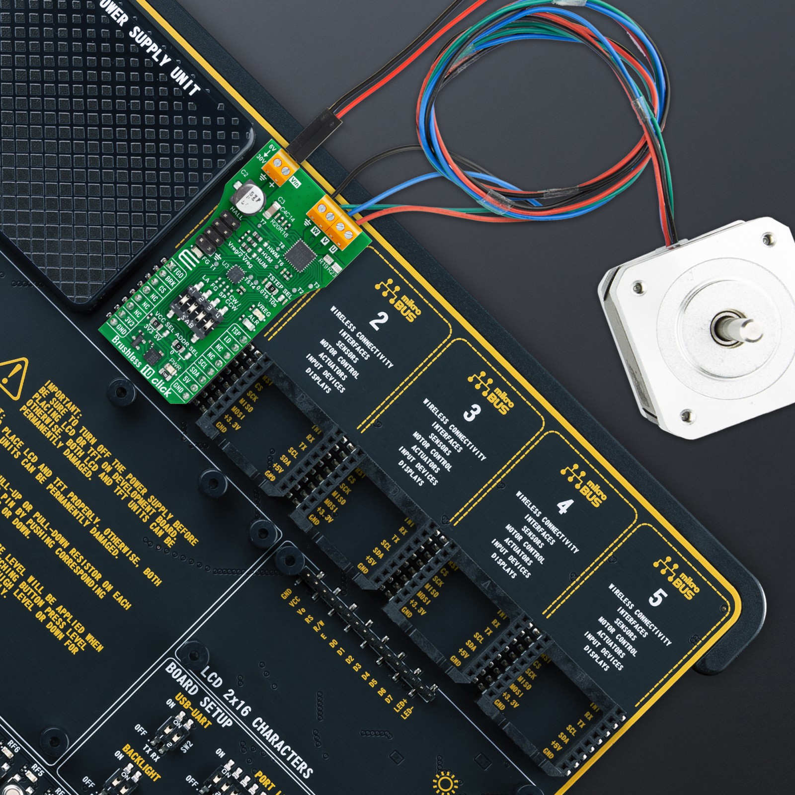
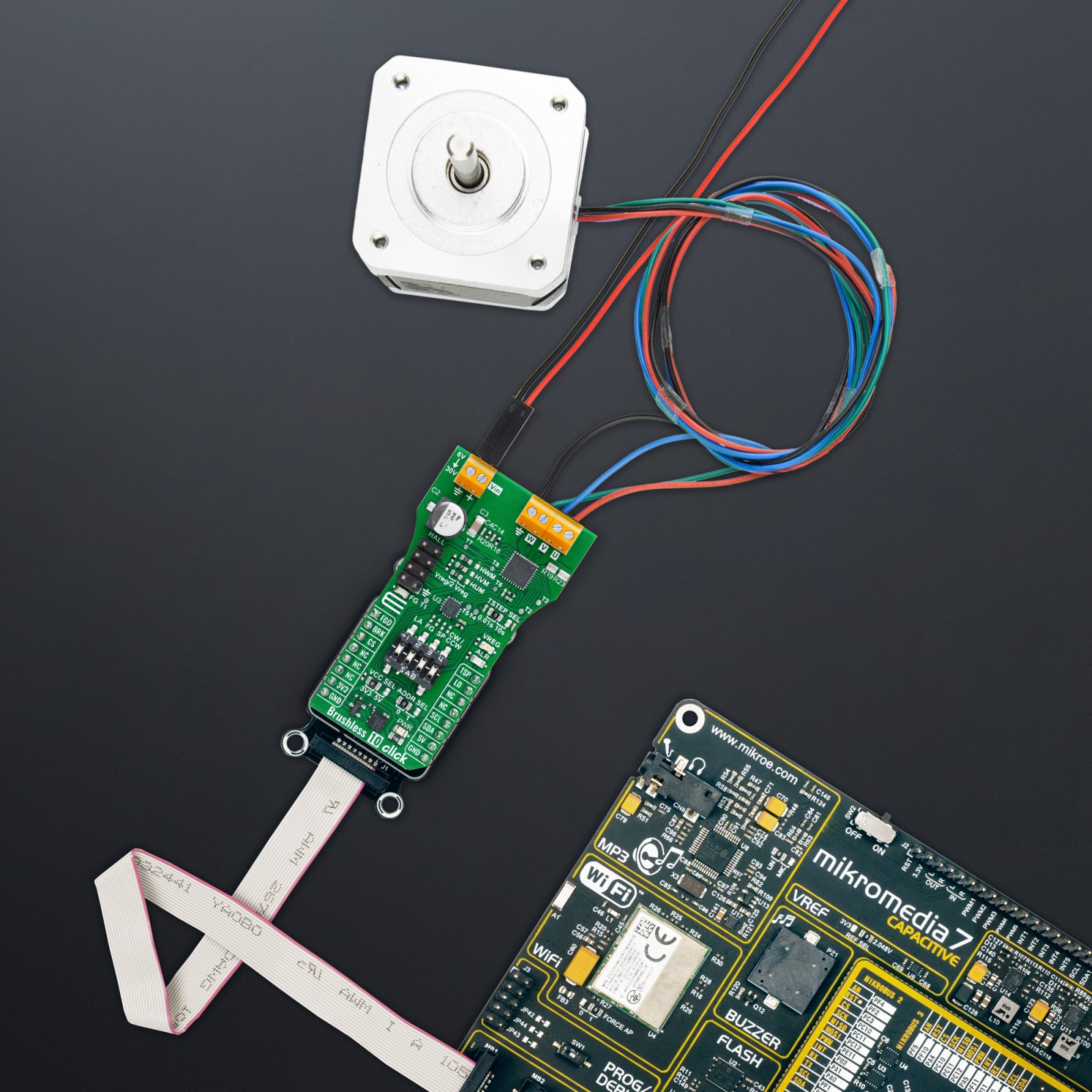
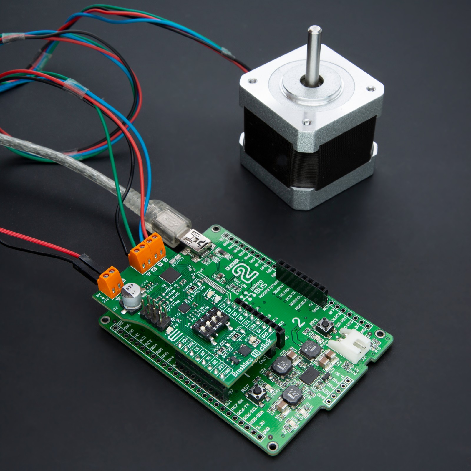
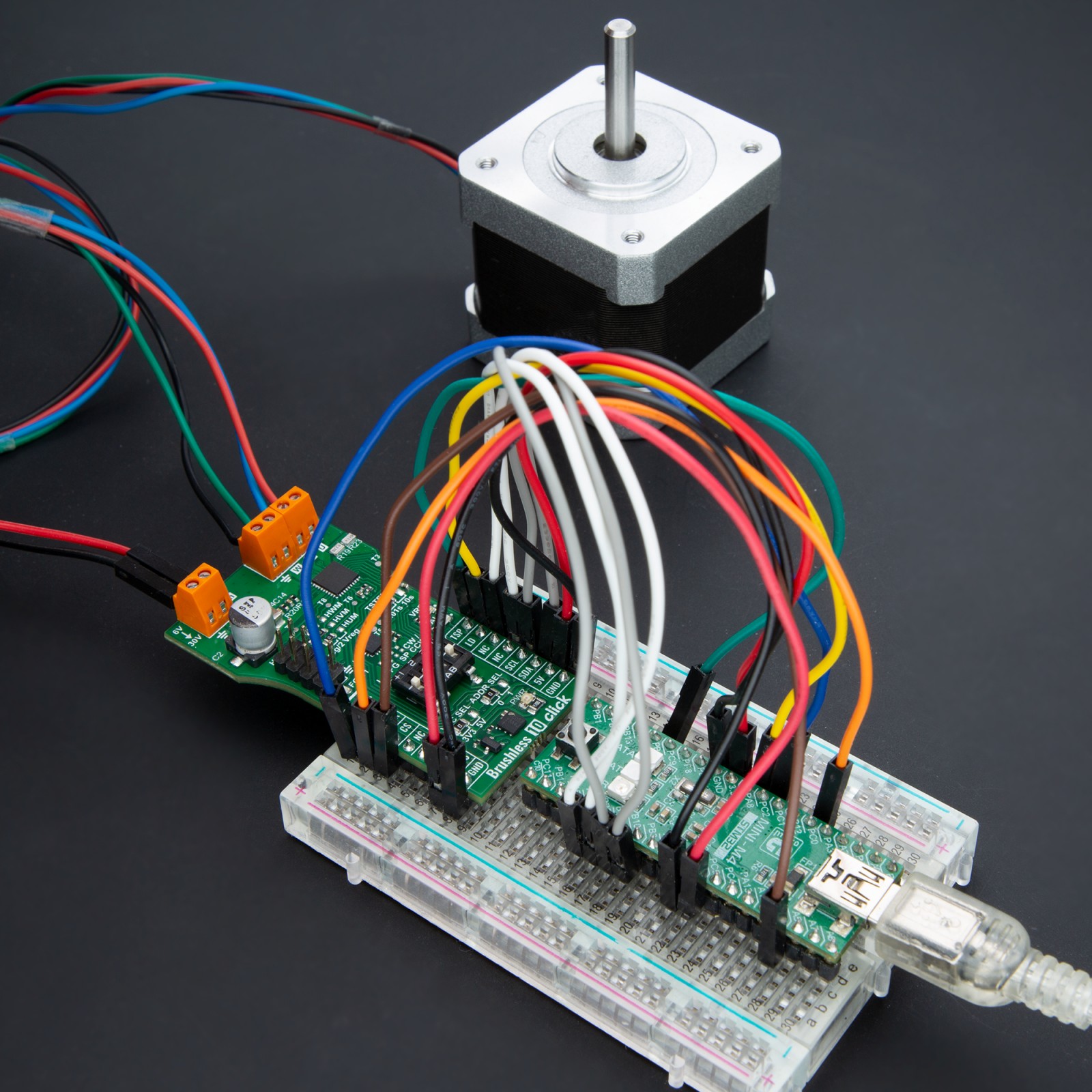
How does it work?
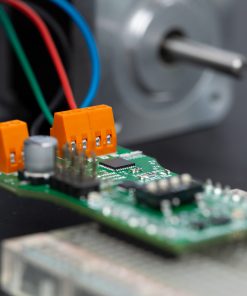
Brushless 10 Click is based on the TC78B016FTG, a 3-phase sine-wave PWM driver for brushless DC motors from Toshiba Semiconductor. This driver is equipped with Toshiba’s Intelligent Phase Control, an advanced feature designed to automate the motor’s phase adjustment. Doing so negates manual calibration, streamlines the setup process, and boosts the motor’s efficiency. Primarily utilized in fan motors, this driver leverages its phase adjustment capability to enhance operational efficiency significantly.
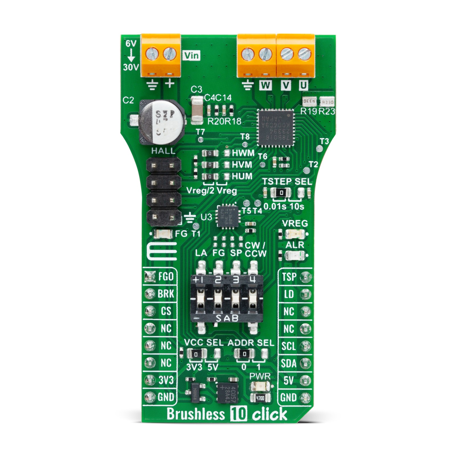
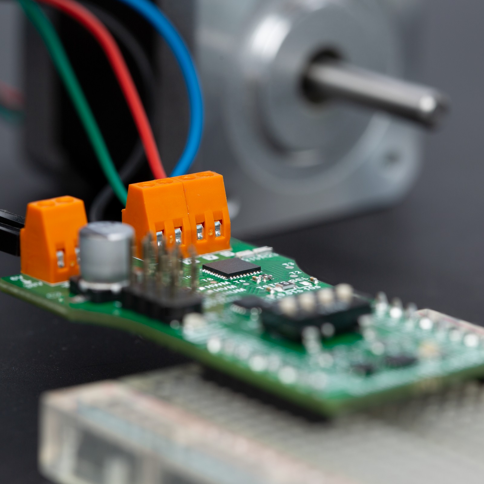
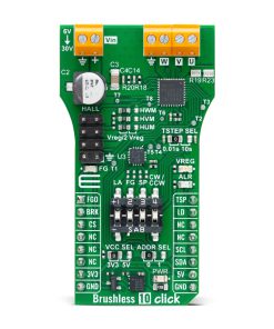
The TC78B016FTG has several control and diagnostic features to effectively manage and monitor brushless DC motors. The FGO (Rotational Speed Output) function produces a rotation pulse derived from hall sensors, offering a choice between one or three pulses per electrical angle, configurable via an FG switch or an onboard DAC if R26 is populated. This allows for a HIGH logic level (logic 1) to emit three pulses per electrical angle and a LOW logic level (logic 0) for one pulse, visually indicating the operational mode by a blue FG LED. The motor operation can be stopped using the BRK pin, where a HIGH logic state activates the Brake function, and a LOW state resumes Normal operation.
Motor speed control is managed through the TSP (Rotational Speed Command) feature, which allows startup, stop, and speed adjustments based on the PWM duty output. This feature is selectable through either analog voltage or pulse duty control, achieved via the SP switch or an onboard DAC if R25 is populated. The LD pin enhances safety by detecting abnormalities such as overcurrent, thermal shutdown, motor lockout, or under/overvoltage conditions, with visual alerts provided by a red ALR LED. Additionally, the board facilitates directional control of the motor, enabling forward or reverse rotation through the CW/CCW switch or an onboard DAC if R22 is populated, with a LOW level for forward and HIGH for setting reverse direction.
The TC78B016FTG’s additional functionalities are tunable via the onboard DAC43608, which interfaces with the host MCU through an I2C connection. This DAC enables the selection of its I2C address through the ADDR SEL jumper by setting it to position 0 or 1, thereby offering a layer of customization for the communication protocol. Various motor control enhancements can be implemented through this DAC, like Lead Angle Control. This feature dynamically improves motor efficiency in response to rotation speed and current variations. This control can be activated using the LA switch for Intelligent Phase Control or Proportion to Frequency adjustments or through an external lead angle control, adjustable via input voltage for a range of 0° to 58° when R27 is populated.
Additionally, it allows for setting a minimum output duty cycle and the configuration of Motor Lockout, determining whether the lockout function is active and its duration of operation versus pause. Furthermore, the DAC enables the selection of the motor’s PWM frequency, offering options of 25kHz, 50kHz, 100kHz, or 200kHz, tailoring the motor’s performance to the application’s needs. Another key feature of this Click board™ is the TSTEP SEL jumper, which performs the acceleration and deceleration control of the motor. This function allows the motor to gradually increase or decrease its speed at startup, with the timing of these transitions adjustable to either 0.01 or 10 seconds based on the jumper’s position.
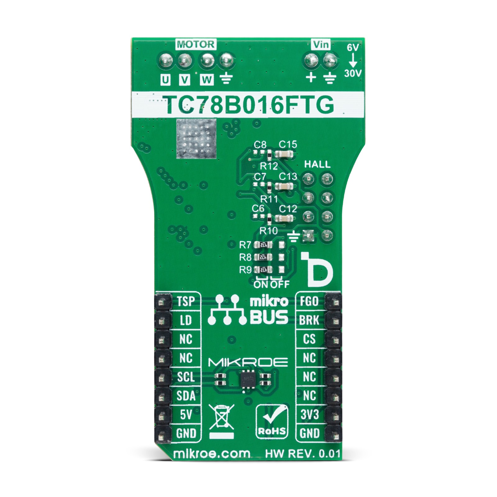
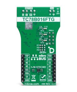
Brushless 10 Click supports an external power supply from 6V to 30V through the VM terminal and allows for current output up to 1.5A, thanks to the R19 and R23 current sense resistors. Based on these populated current sense resistors, which form a value of 150mΩ, the current is rated on 1.5A. This feature ensures that the board can manage various brushless DC (BLDC) motors, including those equipped with Hall sensors, like the BLDC Motor with Hall Sensor offered by MIKROE. In addition to the motor connection terminals, the board is equipped with dedicated pins to connect these additional Hall signals, enhancing the motor’s precision and efficiency. Moreover, the board can fine-tune these Hall signal inputs by using optional 4k7 pull-up resistors, which can be added via jumpers on the back of the board.
Depending on the user’s requirements, these jumpers can be set to an ON or OFF position, offering a layer of customization for signal integrity. Furthermore, this Click board™ is pre-configured for the operational mode of Hall IC usage, with provided additional configuration of Hall U/V/W signals based on a reference voltage provided by the TC78B016FTG. This configuration is set through front-side jumpers to Vreg/2 (2.5V) or Vreg (5V) positions. De-soldering some elements on the board is mandatory in the case of Hall element use. An orange VREG LED visually indicates this reference voltage, ensuring that users can easily verify the board’s status at a glance.
This Click board™ can operate with either 3.3V or 5V logic voltage levels selected via the VCC SEL jumper. This way, both 3.3V and 5V capable MCUs can use the communication lines properly. Also, this Click board™ comes equipped with a library containing easy-to-use functions and an example code that can be used as a reference for further development.
Specifications
Type
Brushless
Applications
Ideal for applications requiring efficient and reliable brushless motor control, such as in fan motors or devices where precise speed and direction control are essential
On-board modules
TC78B016FTG – 3-phase sine-wave PWM driver from Toshiba Semiconductor
Key Features
Built-in auto lead angle architecture (Intelligent Phase Control), Hall amplifier, selectable rotational speed command, selectable PWM frequency, adjustable minimum duty and speed ration in PWM, lead angle control, rotation direction, break, diagnostics, and more
Interface
GPIO,I2C
Feature
ClickID
Compatibility
mikroBUS™
Click board size
L (57.15 x 25.4 mm)
Input Voltage
3.3V or 5V,External
Pinout diagram
This table shows how the pinout on Brushless 10 Click corresponds to the pinout on the mikroBUS™ socket (the latter shown in the two middle columns).
Onboard settings and indicators
Label | Name | Default | Description |
---|---|---|---|
LD1 | PWR | – | Power LED Indicator |
LD2 | VREG | – | Reference Voltage LED Indicator |
LD3 | ALR | – | Anomaly Detection LED Indicator |
LD4 | FG | – | Rotational Speed LED Indicator |
JP1 | VCC SEL | Left | Logic Voltage Level Selection 3V3/5V: Left position 3V3, Right position 5V |
JP2 | ADDR SEL | Left | I2C Address Selection 0/1: Left position 0, Right position 1 |
JP3 | TSTEP SEL | Left | Acceleration/Deceleration Control Selection 0.01s/10s: Left position 0.01s, Right position 10s |
JP4-JP6 | HUM/HVM/HWM | Left | Hall Input Configuration Selection Vreg/2/Vreg: Left position Vreg/2, Right position Vreg |
R7-R9 | R7-R9 | Left | Optional Hall Pull-Ups ON/OFF: Left position ON, Right position OFF |
Brushless 10 Click electrical specifications
Description | Min | Typ | Max | Unit |
---|---|---|---|---|
Supply Voltage | 3.3 | – | 5 | V |
External Power Supply | 6 | – | 30 | V |
Maximum Drive Current | – | 1.5 | – | A |
Software Support
We provide a library for the Brushless 10 Click as well as a demo application (example), developed using MIKROE compilers. The demo can run on all the main MIKROE development boards.
Package can be downloaded/installed directly from NECTO Studio Package Manager(recommended), downloaded from our LibStock™ or found on Mikroe github account.
Library Description
This library contains API for Brushless 10 Click driver.
Key functions
-
brushless10_set_duty_cycle
This function sets the PWM duty cycle in percentages ( Range[ 0..1 ] ). -
brushless10_pull_brake
This function pulls brake by setting the BRAKE pin to high logic state. -
brushless10_release_brake
This function releases brake by setting the BRAKE pin to low logic state.
Example Description
This example demonstrates the use of the Brushless 10 Click board™ by driving the motor at different speeds.
void application_task ( void )
{
static int8_t duty_cnt = 2;
static int8_t duty_inc = 1;
float duty = duty_cnt / 10.0;
brushless10_set_duty_cycle ( &brushless10, duty );
log_printf( &logger, "> Duty: %d%%rn", ( uint16_t )( duty_cnt * 10 ) );
Delay_ms( 2000 );
duty_cnt += duty_inc;
if ( duty_cnt > 10 )
{
duty_cnt = 9;
duty_inc = -1;
}
else if ( duty_cnt < 2 )
{
duty_cnt = 2;
duty_inc = 1;
log_printf( &logger, " Pull brakern" );
brushless10_pull_brake ( &brushless10 );
Delay_ms( 3000 );
log_printf( &logger, " Release brakern" );
brushless10_release_brake ( &brushless10 );
Delay_ms( 1000 );
}
}
The full application code, and ready to use projects can be installed directly from NECTO Studio Package Manager(recommended), downloaded from our LibStock™ or found on Mikroe github account.
Other Mikroe Libraries used in the example:
- MikroSDK.Board
- MikroSDK.Log
- Click.Brushless10
Additional notes and informations
Depending on the development board you are using, you may need USB UART click, USB UART 2 Click or RS232 Click to connect to your PC, for development systems with no UART to USB interface available on the board. UART terminal is available in all MIKROE compilers.
mikroSDK
This Click board™ is supported with mikroSDK – MIKROE Software Development Kit. To ensure proper operation of mikroSDK compliant Click board™ demo applications, mikroSDK should be downloaded from the LibStock and installed for the compiler you are using.
For more information about mikroSDK, visit the official page.