How does it work?
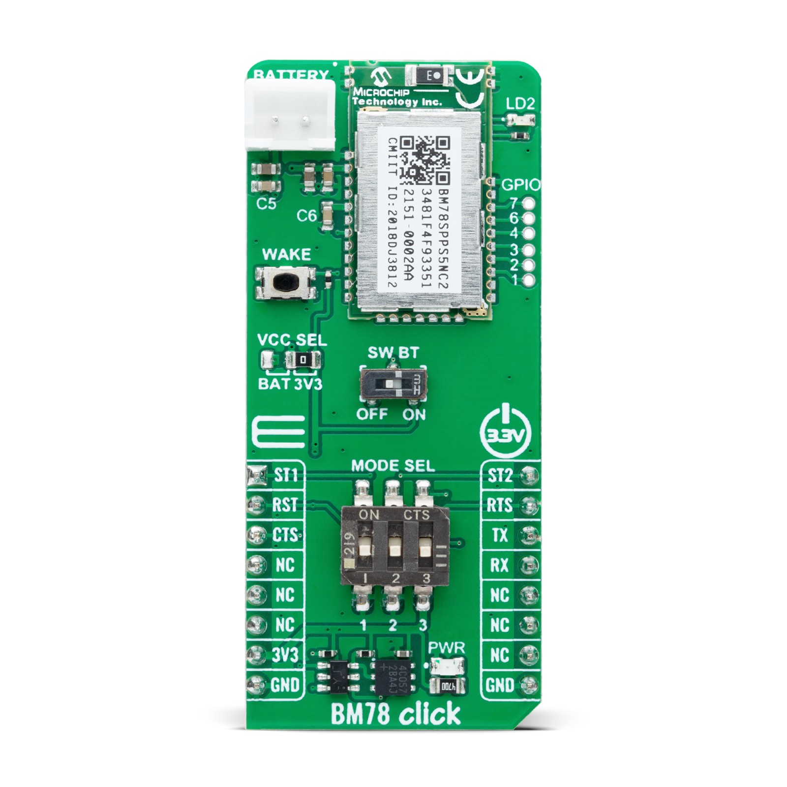
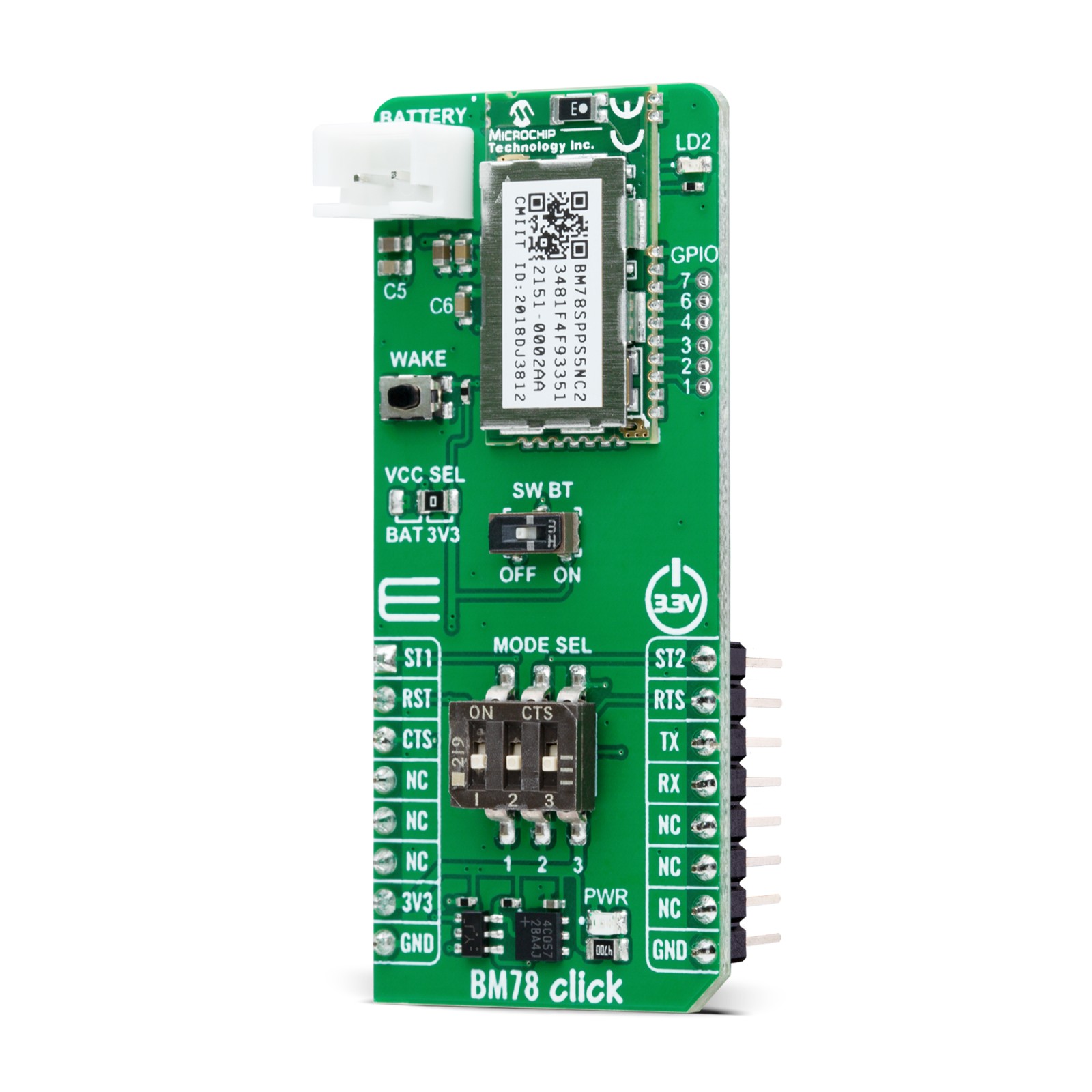
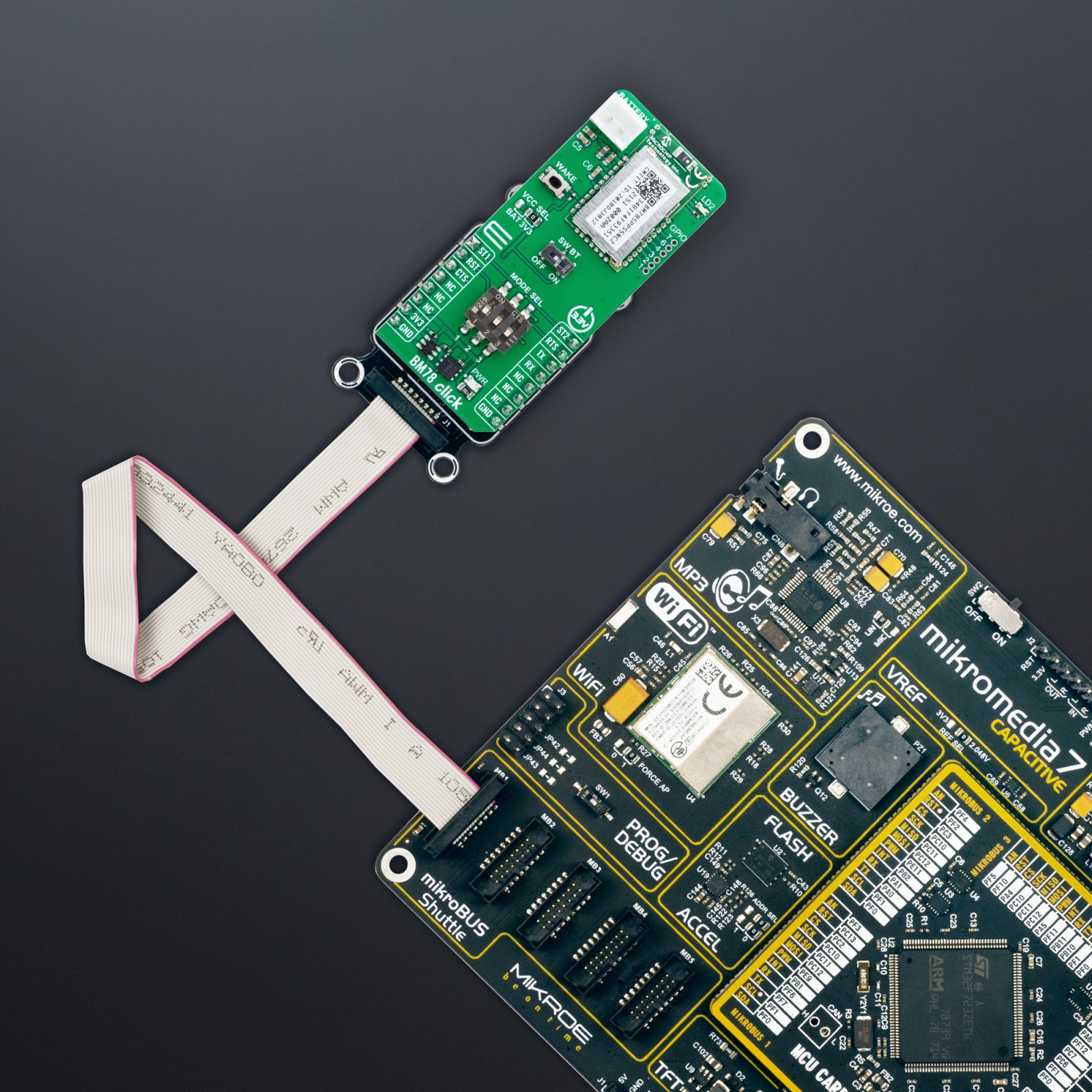
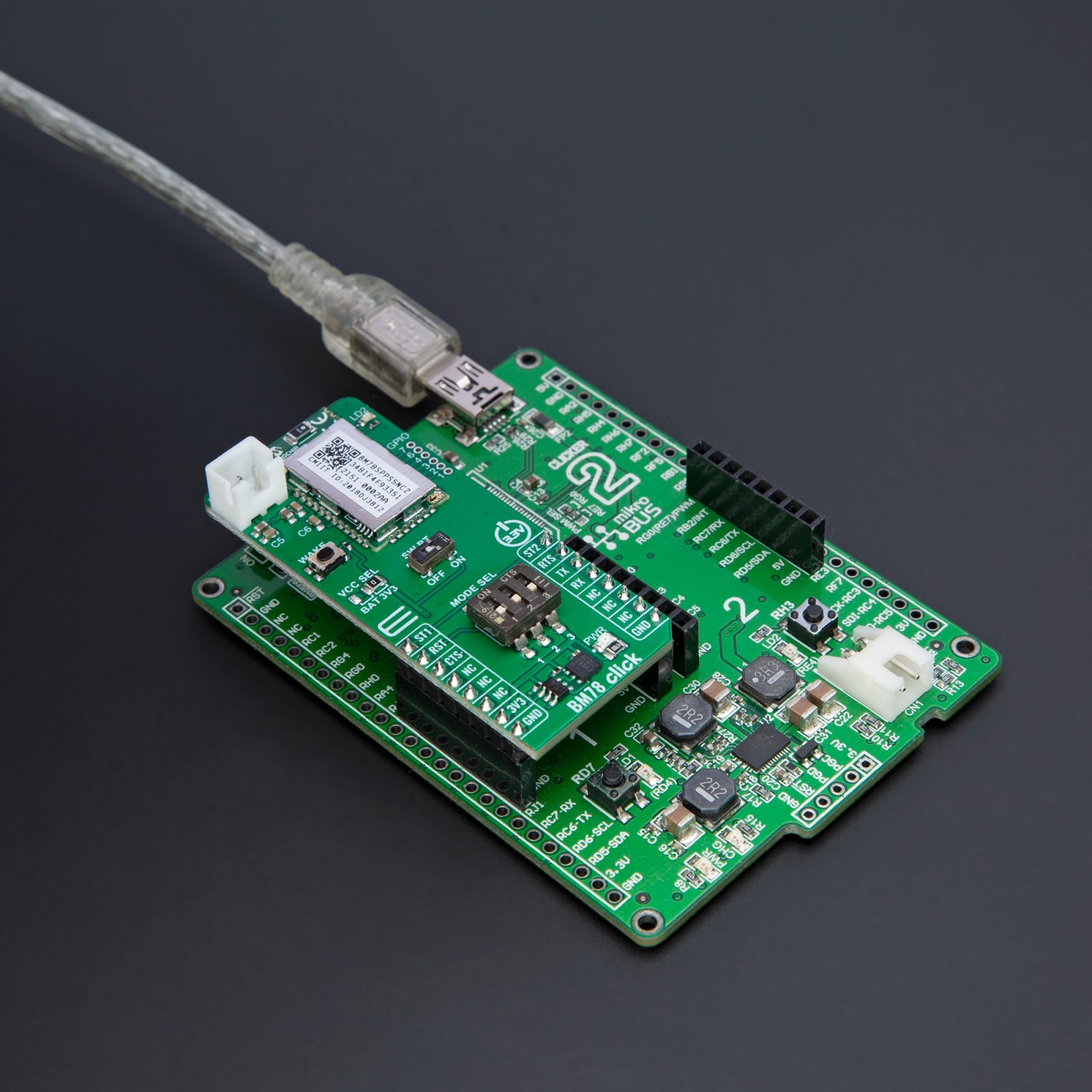
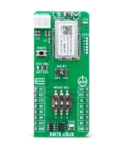
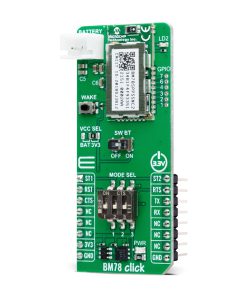
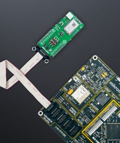
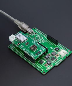
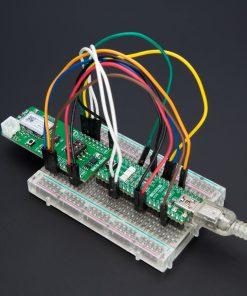
BM78 Click is based on the BM78, a fully certified 2.4GHz Bluetooth (BR/EDR/LE) wireless module from Microchip. It is designed to integrate dual-mode Bluetooth wireless capability into various projects easily. The BM78 is built around Microchip’s IS1678 Bluetooth Dual mode SoC, specifically the ROM-based BM78SPPS5NC2 version. The module includes an on-board Bluetooth stack, power management subsystem, 2.4GHz transceiver, and RF power amplifier. It supports GAP, SDP, SPP, and GATT profiles, enabling data transfer through transparent UART mode for easy integration with any MCU with a UART interface. This makes it ideal for connecting products to smartphones or tablets for convenient data transfer, control, cloud application access, and local connectivity for IoT, secure payment systems, home automation, security, industrial applications, and data logging.
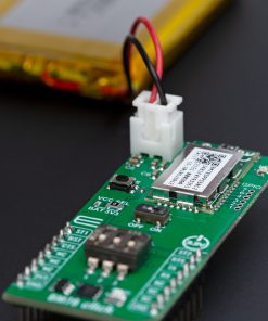
BM78 Click provides flexibility with two operational modes: Auto-Pattern and Manual-Pattern. These modes use different state machines and can be selected by setting the appropriate value in the EEPROM memory. By default, the BM78 module operates in Auto-Pattern mode. The board also includes a MODE SEL switch that allows users to set the module in one of two modes: application mode for normal operation or test mode to change EEPROM values. The module operates normally when all three switches are in the HIGH position. The module enters test mode if only the first switch (1) is in the LOW position.
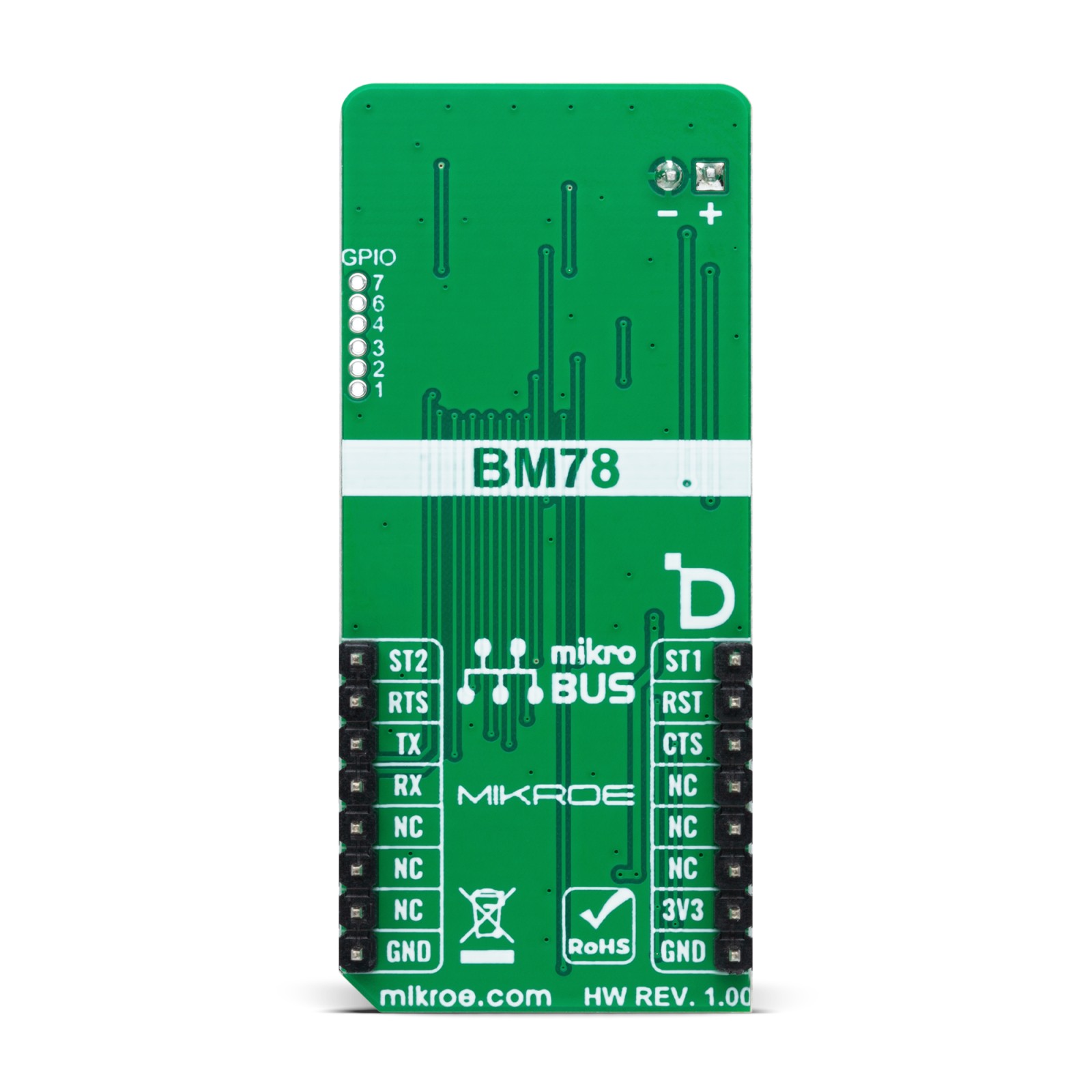
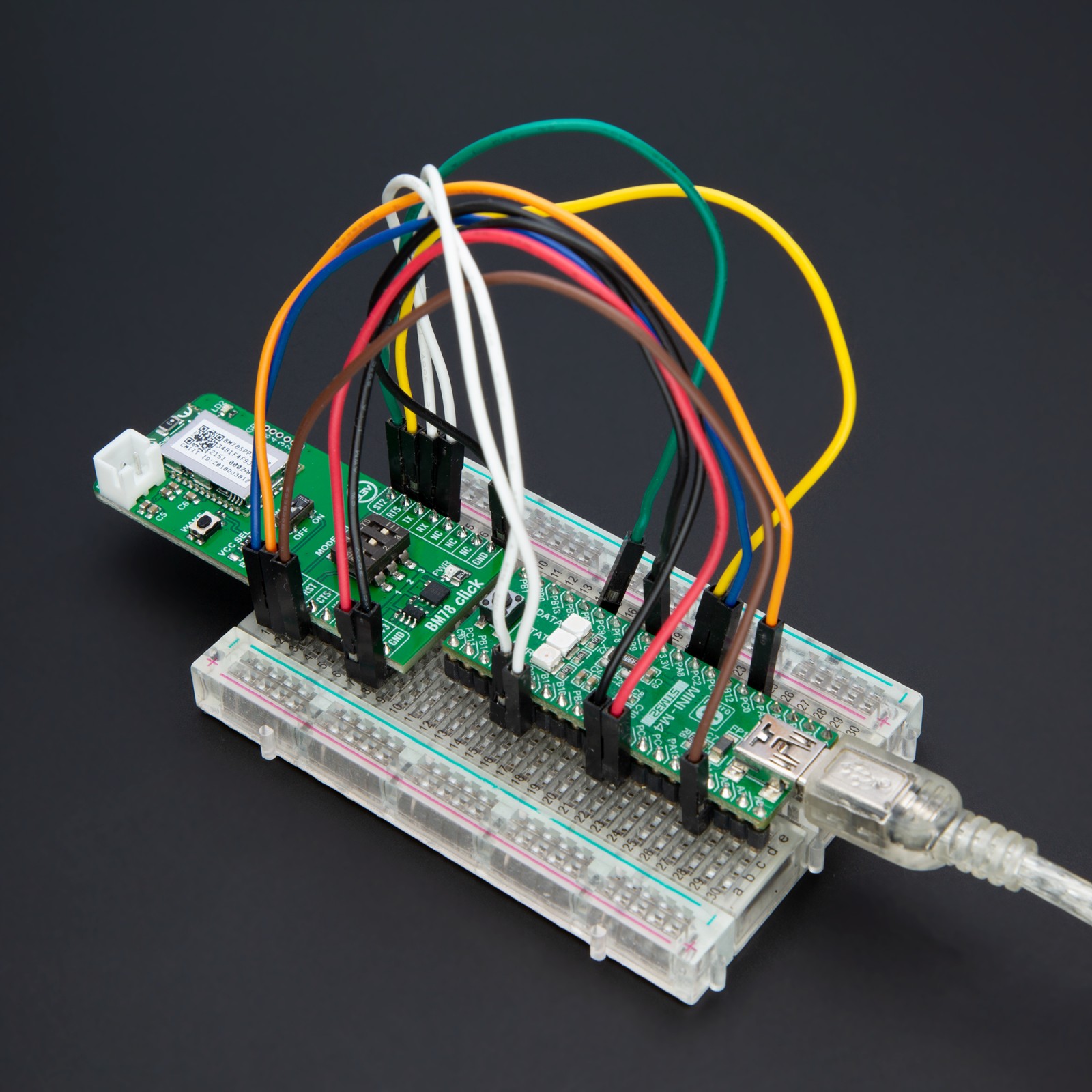
As mentioned, communication between the BM78 and the host MCU is made through a UART interface, standard UART RX and TX pins, and hardware flow control pins (CTS and RTS) for efficient data transfer. The BM78 Click also features a reset (RST) pin for hard resetting the module and two status indicators on the ST1 and ST2 pins. These pins provide various status indications to the host MCU, such as Power-On, deep state, access state, and link state indications, showing whether UART data is being transmitted or not.
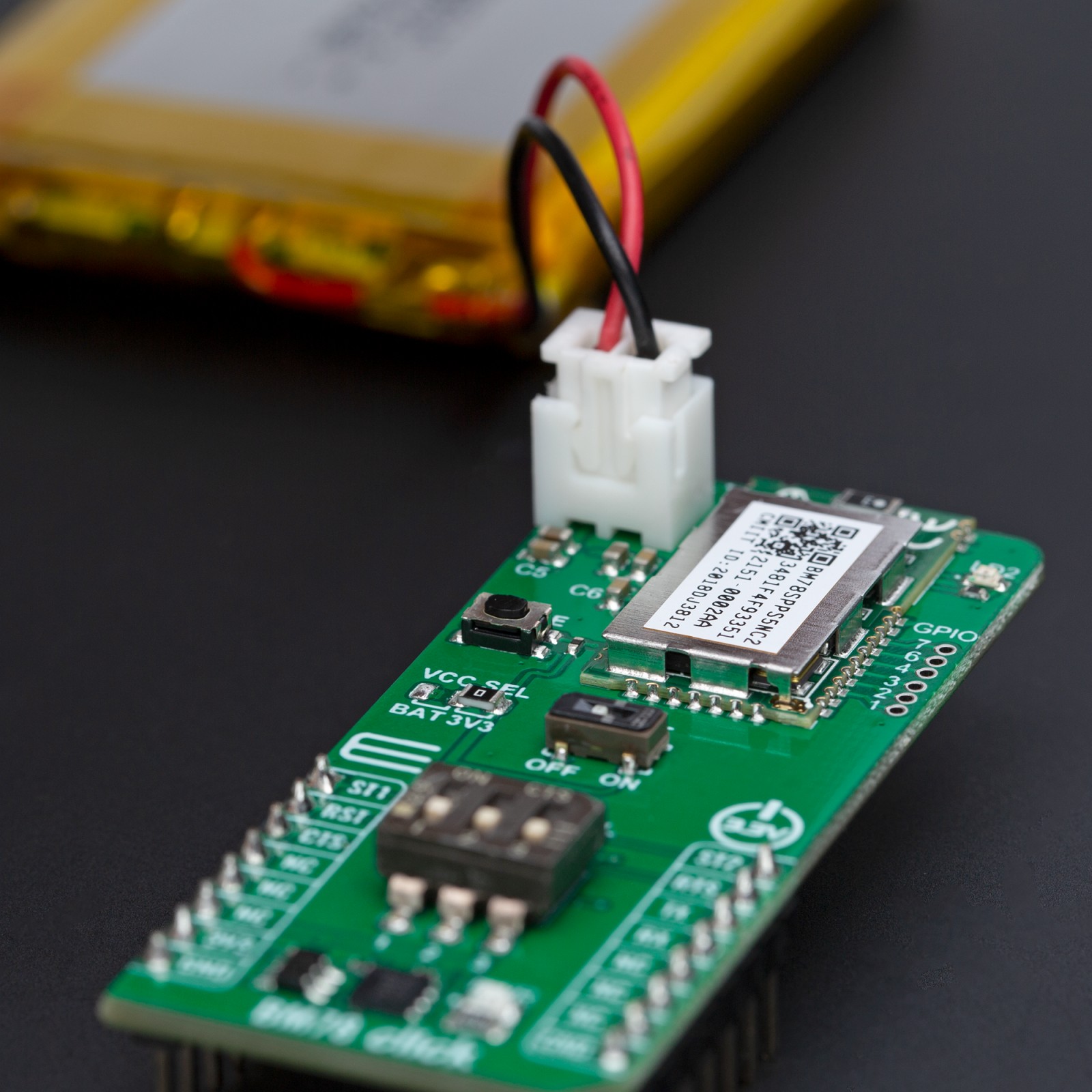
In addition, this board also includes a SW BT switch, which acts as a software power button, allowing the user to power the BM78 module ON (high) or switch it OFF (low) into Deep Sleep mode to reduce power consumption. Also, the board features a WAKE button, which transitions the module from Sleep mode to Standby mode, a user-configurable red LED indicator labeled LD2, which indicates various statuses such as standby, link back, low battery, inquiry, or link, and two unpopulated 1×3 headers that provide access to several I/O pins of the BM78. These pins can perform multiple functions, including low battery indication, RSSI, link drop, UART RX, pairing key, and inquiry control, among others.
This Click board™, and the module itself, can be operated only with a 3.3V logic voltage level. For this reason, in addition to being powered via a mikroBUS™ socket, users can also opt for external battery power, with power selection managed through the VCC SEL jumper. The board must perform appropriate logic voltage level conversion before using MCUs with different logic levels. Also, it comes equipped with a library containing functions and an example code that can be used as a reference for further development.
Specifications
Type
BT/BLE
Applications
Ideal for IoT, secure payment systems, home automation, security, industrial applications, and data logging
On-board modules
BM78 – fully certified 2.4GHz Bluetooth (BR/EDR/LE) wireless module from Microchip
Key Features
On-board Bluetooth stack, power management subsystem, 2.4GHz transceiver, RF power amplifier, supports multiple Bluetooth profiles such as GAP, SDP, SPP, and GATT, UART interface, MODE SEL switch for selecting operational modes, reset feature, status indicators for various states, a software power button for deep sleep mode, and more
Interface
UART
Feature
ClickID
Compatibility
mikroBUS™
Click board size
L (57.15 x 25.4 mm)
Input Voltage
3.3V,External
Pinout diagram
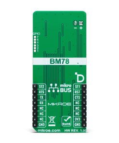
This table shows how the pinout on BM78 Click corresponds to the pinout on the mikroBUS™ socket (the latter shown in the two middle columns).
Onboard settings and indicators
Label | Name | Default | Description |
---|---|---|---|
LD1 | PWR | – | Power LED Indicator |
LD2 | LD2 | – | User-Configurable LED Indicator |
JP1 | VCC SEL | Right | Module Power Supply Selection BAT/3V3: Left position BAT, Right position 3V3 |
SW1 | MODE SEL | – | Mode Selection Switch |
SW2 | SW BT | – | Software Power Switch |
T1 | WAKE | – | Module Wake-Up Button |
BM78 Click electrical specifications
Description | Min | Typ | Max | Unit |
---|---|---|---|---|
Supply Voltage | – | 3.3 | – | V |
Frequency Range | 2.402 | – | 2.480 | GHz |
Receiver Sensitivity | -90 | – | -92 | dBm |
Output Power | – | +1.5 | – | dBm |
Software Support
We provide a library for the BM78 Click as well as a demo application (example), developed using MIKROE compilers. The demo can run on all the main MIKROE development boards.
Package can be downloaded/installed directly from NECTO Studio Package Manager (recommended), downloaded from our LibStock™ or found on MIKROE github account.
Library Description
This library contains API for BM78 Click driver.
Key functions
-
bm78_eeprom_send_cmd
This function is used to send specific EEPROM command by using UART serial interface. -
bm78_eeprom_write
This function is used to write data into the EEPROM location specified by the address parameter. -
bm78_flash_eeprom
This function is used write default configuration into the EEPROM.
Example Description
This example demonstrates the use of BM78 Click by processing the incoming data and displaying them on the USB UART.
void application_task ( void )
{
if ( BM78_OK == bm78_process( &bm78 ) )
{
bm78_log_app_buf( );
bm78_clear_app_buf( );
}
}
The full application code, and ready to use projects can be installed directly from NECTO Studio Package Manager (recommended), downloaded from our LibStock™ or found on MIKROE github account.
Other MIKROE Libraries used in the example:
- MikroSDK.Board
- MikroSDK.Log
- Click.BM78
Additional notes and informations
Depending on the development board you are using, you may need USB UART click, USB UART 2 Click or RS232 Click to connect to your PC, for development systems with no UART to USB interface available on the board. UART terminal is available in all MIKROE compilers.
mikroSDK
This Click board™ is supported with mikroSDK – MIKROE Software Development Kit. To ensure proper operation of mikroSDK compliant Click board™ demo applications, mikroSDK should be downloaded from the LibStock and installed for the compiler you are using.
For more information about mikroSDK, visit the official page.