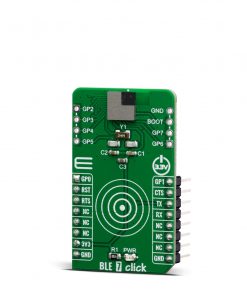
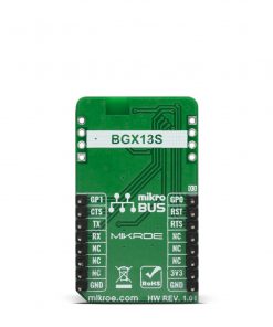
BLE 7 Click
R445.00 ex. VAT
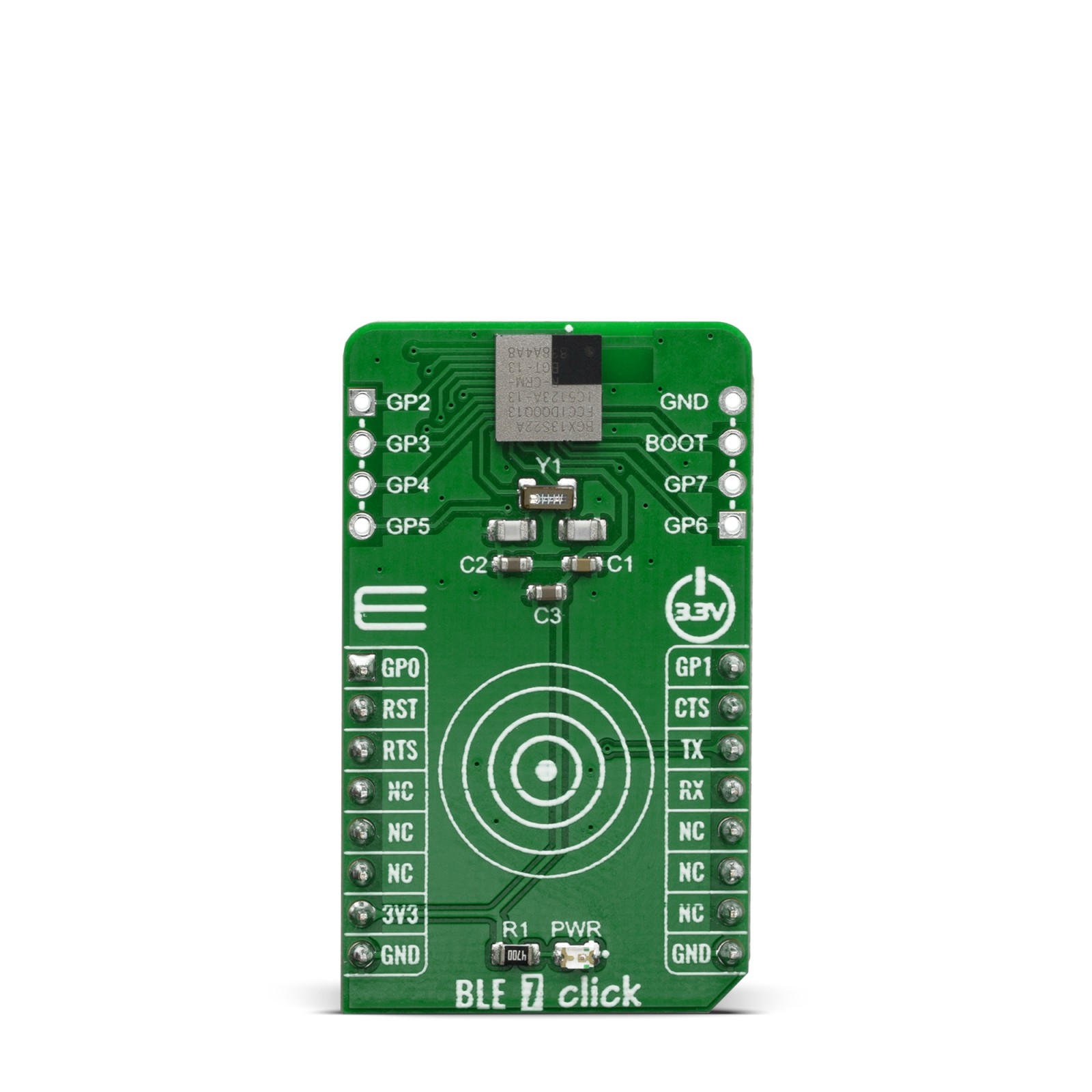
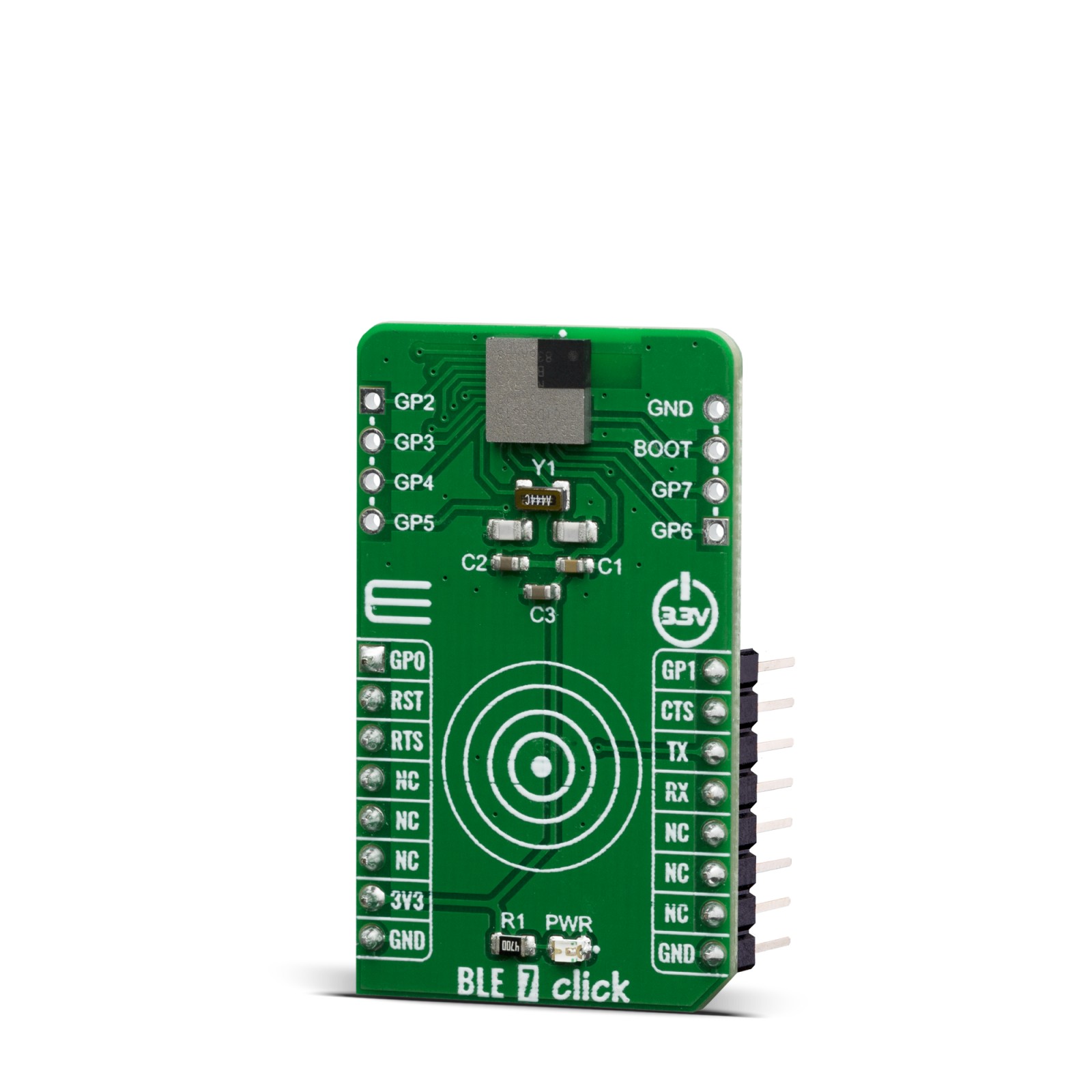
The BLE 7 click is a Click board™ witch provide BT/BLE connectivity for any embedded application. BLE 7 click based on the BGX13S22GA-V31, a SiP module from Silicon Labs with a buit-in antenna. Click board™ an ultra-small, high-performing, Bluetooth low energy module for easy integration of Bluetooth low energy connectivity (BLE) into various electronic devices. Given its features, this click can be used for health, sports, and wellness devices as well as Industrial, home, and building automation; and smart phone, tablet, and PC accessories.
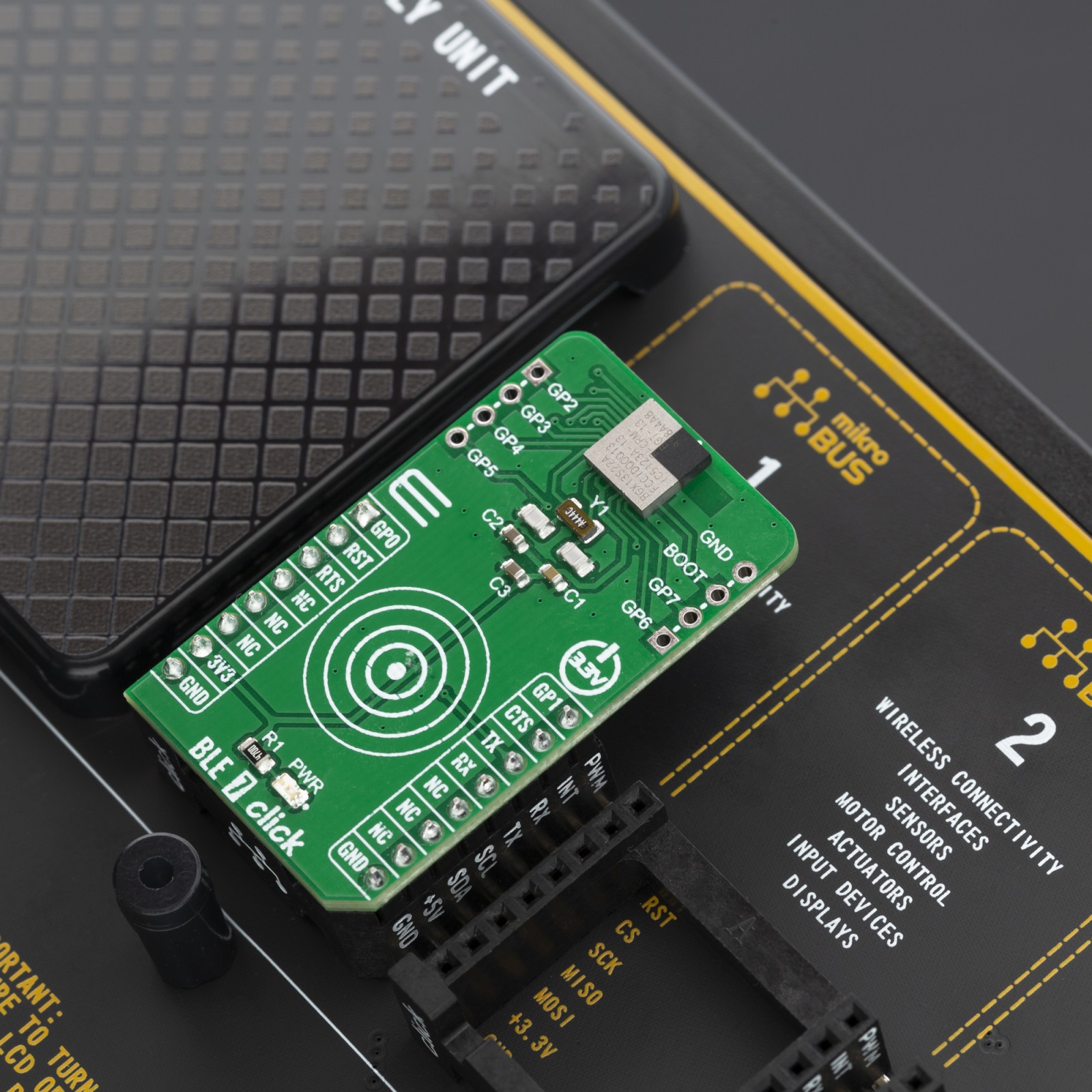
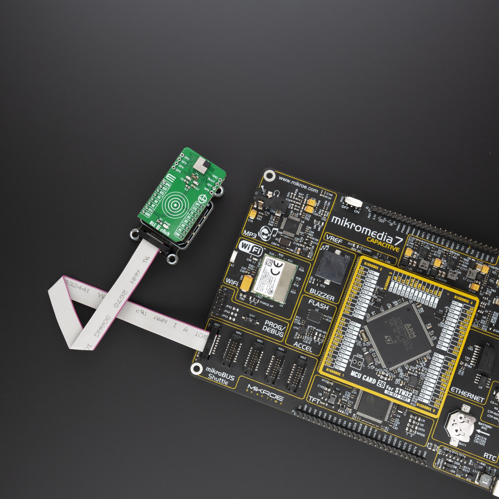
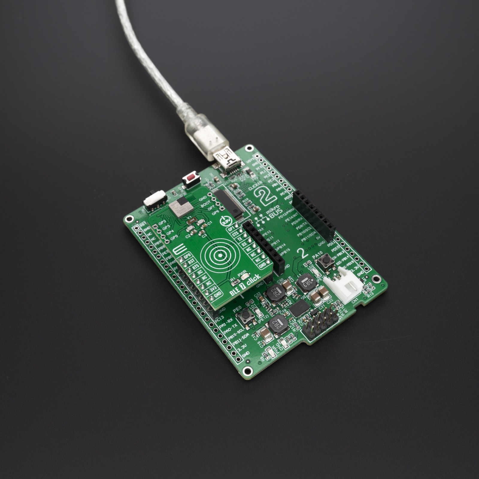
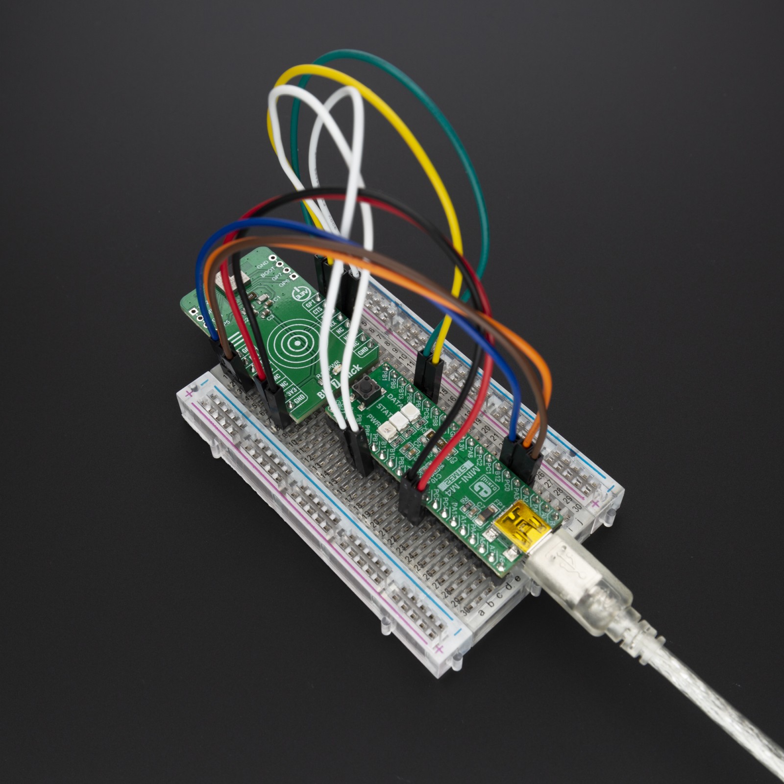
BLE 7 click is supported by a mikroSDK compliant library, which includes functions that simplify software development. This Click board™ comes as a fully tested product, ready to be used on a system equipped with the mikroBUS™ socket.
Stock: Lead-time applicable.
| 5+ | R422.75 |
| 10+ | R400.50 |
| 15+ | R378.25 |
| 20+ | R364.01 |
How does it work?
The BLE 7 click is a Click board™ based on the BGX13S22GA-V31, a module from Silicon Labs that has some impressive features including the fact that it is Bluetooth 5 low energy compliant, GPIO control through command API, Encrypted bonding and connectivity and an Integrated DC-DC Converter.
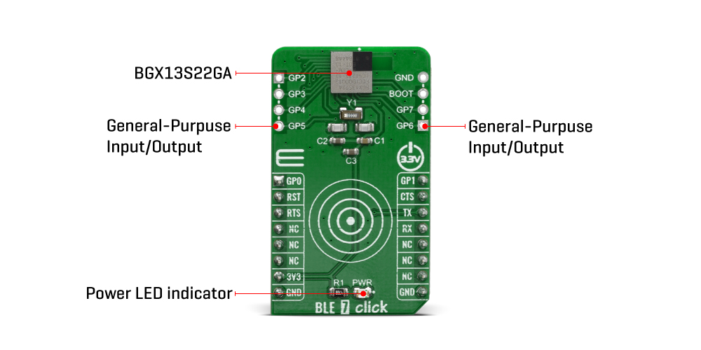
The BGX13S22GA-V31 module eliminates Bluetooth firmware development complexity with a serial interface that can operate as a raw data stream or control the device through a abstracted command API. The BGX13S22GA-V31 can facilitate a device-to-device cable replacement link or communicate with mobile devices through the Xpress Bluetooth mobile library. The device integrates a Bluetooth 5 compliant stack to future-proof applications as Bluetooth 5 adoption increases. The device is targeted for applications where ultra-small size, reliable high-performance RF, low-power consumption, and fast time-to-market are key requirements.
BGX13S22GA-V31 also integrates a high-performance, ultra-robust antenna, which requires minimal PCB, plastic, and metal clearance.
Minimum and maximum values represent the worst conditions across supply voltage, process variation, and operating temperature, unless stated otherwise. The BGX13S module has only one external supply pin (VDD). There are several internal supply rails mentioned in the electrical specifications, whose connections vary based on transmit power configuration.
The BGX13S creates a Bluetooth 5 compliant BLE cable replacement interface, facilitating a BLE link to a second embedded device or a mobile device. An embedded MCU controls the device and communicates across the BLE link through a serial interface and control signals. Parameters stored in non-volatile memory and configurable through the serial interface adjust performance characteristics of the device. Silicon Labs offers iOS and Android mobile libraries for Blue Gecko Xpress devices to speed mobile development and simplify communication with the device.
This Click Board™ is designed to be operated only with 3.3V logic level. A proper logic voltage level conversion should be performed before the Click board™ is used with MCUs with logic levels of 5V.
Specifications
Type
BT/BLE
Applications
Health, sports, and wellness devices as well as Industrial, home, and building automation; and smart phone, tablet, and PC accessories
On-board modules
BGX13S22GA-V31, Bluetooth 5 low energy module from Silicon Labs
Key Features
Bluetooth 5 low energy compliant, integrated antenna, Tx power up to 8 dBm
Interface
GPIO,UART
Feature
No ClickID
Compatibility
mikroBUS™
Click board size
M (42.9 x 25.4 mm)
Input Voltage
3.3V
Pinout diagram
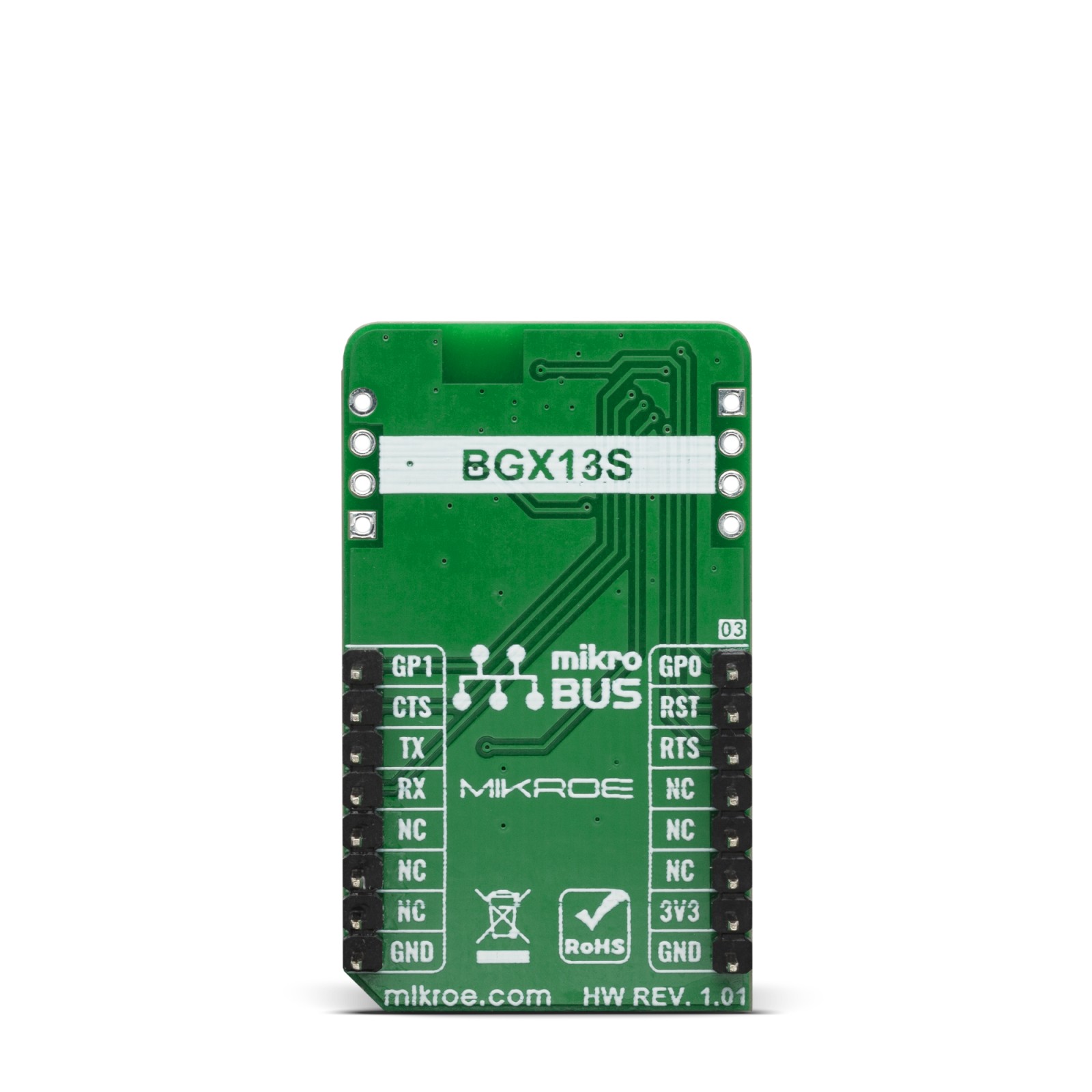
This table shows how the pinout on BLE 7 click corresponds to the pinout on the mikroBUS™ socket (the latter shown in the two middle columns).
Onboard settings and indicators
| Label | Name | Default | Description |
|---|---|---|---|
| LD1 | PWR | – | Power LED Indicator |
| J1 | – | – | General-Purpose Input/Output |
| J2 | – | – | General-Purpose Input/Output |
Software Support
We provide a library for the BLE 7 Click on our LibStock page, as well as a demo application (example), developed using MikroElektronika compilers. The demo can run on all the main MikroElektronika development boards.
Library Description
This library offers a choice to communicate with the BLE 7 Click board (BGX 13P22GAV21 module). Library can send commands, configurations, status request, pairing request or any other data. Also can receive any response from the BGX module, including confirmed or unconfirmed response (answer), module status, connection status, and any transferred data from the other BGX module. Any BLE 7 click can be configured to work as central (server, master) device or as peripheral (client, slave) device. For more details check documentation.
Key functions:
void ble7_uart_isr( void )– This function reads response bytes from the BGX module and sets flag after each received byteuint8_t ble7_response_ready( void )– This function checks does response ready or not.void ble7_send( uint8_t *tx_data )– This function allows user to transmit data to the BGX module.
Examples description
The application is composed of three sections :
- System Initialization – Initializes peripherals and pins.
- Application Initialization – Initializes UART serial interface, uart interrupt, and executes the module reset.
- Application Task – (code snippet) – This function has two segments. First segment allows user to enter a commands, module configuration, data which will be transmitted, also to check all module and connection status by using the serial terminal. Press ‘enter’ when you want to send the entered command (data). Press ‘backspace’ to delete the wrong entered character before you send the command. Press ‘up-down’ or ‘left-right’ to see and enter the 3 last sent commands. Second segment allows user to check and get response from the module when response was ready. Note : The all possible commands and module configurations can be found on the next link: https://docs.silabs.com/gecko-os/1/bgx/latest/commands
void applicationTask()
{
    rx_data = UART_Rdy_Ptr();

    if (rx_data != _RX_NOT_READY)
    {
        rx_data = UART_Rd_Ptr();

        checkRX();
    }

    logRsp();
}
Additional Functions :
- _strcpy – Allows user to copy content of one string to another string, starting from the first place.
- prevCmd – Checks which character (up, down, left, right) was entered by the user.
- checkPrevCmd – Determines which of the 3 previous commands will be entered again.
- checkRX – Checks which character was entered by the user and executes a operation which is determined with the entered character.
- getRsp – Catches the response bytes and sets flag when the response was ready.
- logRsp – Allows user to see and check the response on the serial terminal.
- interrupt – Checks does any new byte was received from the module.
The full application code, and ready to use projects can be found on our LibStock page.
Other mikroE Libraries used in the example:
- UART
Additional notes and informations
Depending on the development board you are using, you may need USB UART click, USB UART 2 click or RS232 click to connect to your PC, for development systems with no UART to USB interface available on the board. The terminal available in all MikroElektronika compilers, or any other terminal application of your choice, can be used to read the message.
mikroSDK
This Click board™ is supported with mikroSDK – MikroElektronika Software Development Kit. To ensure proper operation of mikroSDK compliant Click board™ demo applications, mikroSDK should be downloaded from the LibStock and installed for the compiler you are using.
For more information about mikroSDK, visit the official page.
Resources
Downloads
| Weight | 17 g |
|---|---|
| Brand | MikroElektronika |

