How does it work?
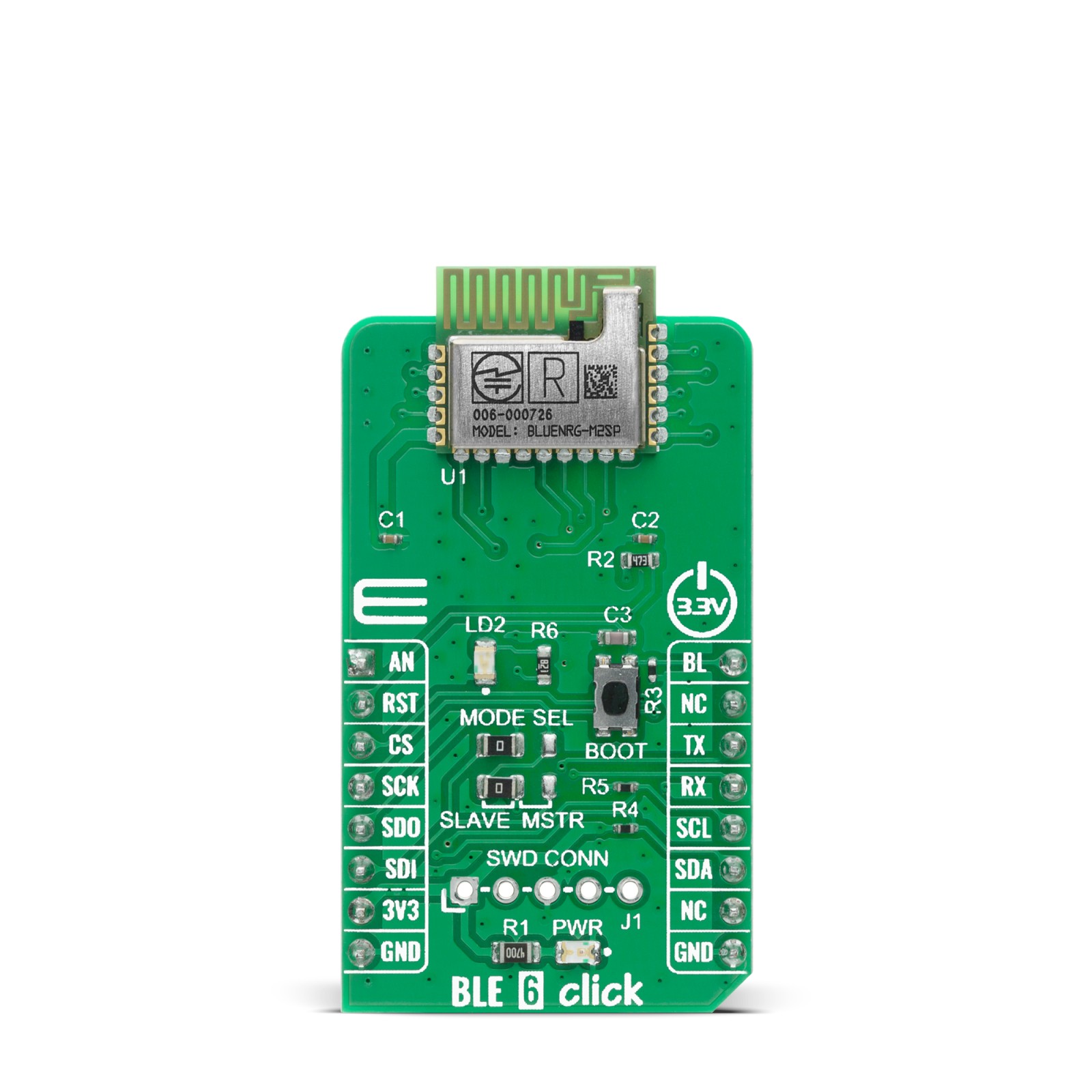
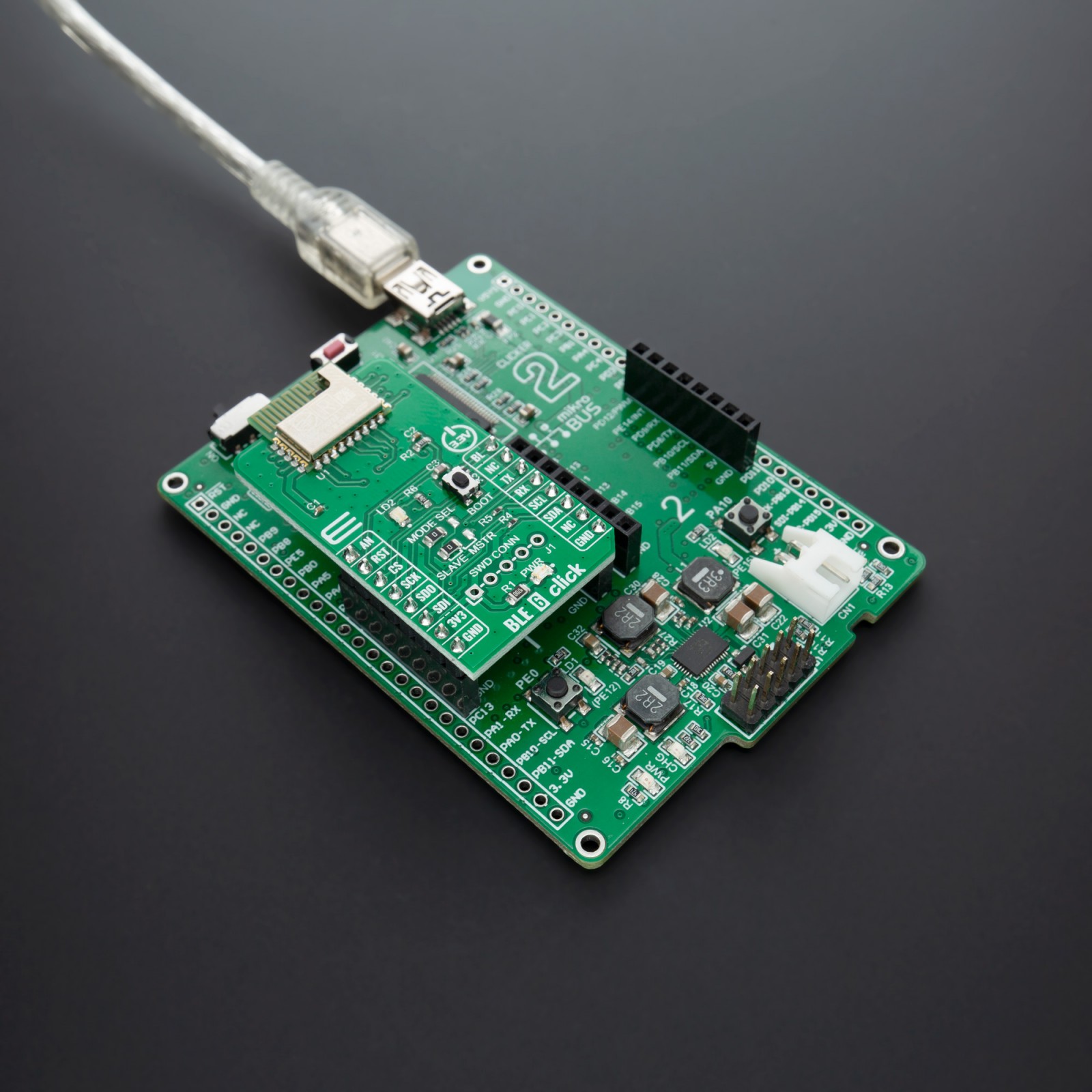
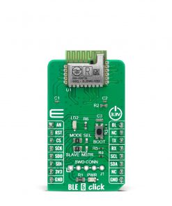
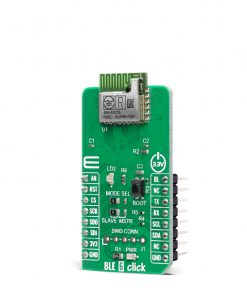
BLE 6 Click uses the BlueNRG-M2, a Bluetooth low energy application processor module compliant with Bluetooth® v5.0. The BlueNRG-M2 module has been designed around the ST BlueNRG-2 SoC where its Cortex-M0 core can execute both Bluetooth protocols and customer application. Optimized memory architecture includes 256 kB of Flash memory and 24 kB of ultra-low-leakage RAM (with full data retention). A complete power-optimized Bluetooth stack library provides:
- Master, slave and multiple role support;
- GAP: central, peripheral, observer or broadcaster roles;
- Simultaneous advertising and scanning;
- Capability of being a slave of up to two masters simultaneously;
- ATT/GATT: client and server;
- SM: privacy, authentication and authorization;
- L2CAP;
- Link Layer: AES-128 encryption and decryption.
The BLUENRG-M2 module has both 32 MHz and 32 kHz crystal oscillators implemented. It has been designed to leverage the BlueNRG-2 integrated DC-DC step-down converter in order to achieve the best power consumption in active mode. It also embeds a high-efficiency chip antenna. It can be configured to support both application processor (host-less) and network processor (hosted) modes. The BlueNRG-M2 module provides a complete RF application platform in a tiny form factor (11.5 x 13.5 x 2.0 mm) and being a certified solution optimizes the time to market of the final applications. The BlueNRG-M2 module allows applications to meet the tight advisable peak current requirements imposed with the use of standard coin cell batteries.
There are two possible software architectures: Host-less mode (application processor – customer application runs on the BlueNRG-M2 module) and Hosted mode (network processor – the module is configured as network module controlled by an external host connected via SPI or UART). The module comes with a pre-programmed UART bootloader. The BlueNRG-M2 embeds the ARM serial wire debug (SWD) port routed to the SWD header connector. It is two pin (clock and single bi-directional data) debug interface, providing all the debug functionality plus real-time access to system memory without halting the processor or requiring any target resident code. Since the SPI peripheral can be used either as master or slave, the onboard SMD jumpers labeled as MODE SEL allow switching between the two.
This Click Board™ is designed to be operated only with a 3.3V logic level. A proper logic voltage level conversion should be performed before the Click board™ is used with MCUs with logic levels of 5V.
Specifications
Type
BT/BLE
Applications
Internet of Things, Smart Home, Building and industrial automation, Smart Lighting, Remote and access control, Fitness, wellness and sports, Consumer medical, Security and proximity, Assisted living, PC and smartphone peripherals
On-board modules
BLE 6 Click uses the BlueNRG-M2 module, a Bluetooth low energy system-on-chip application processor certified module, from STMicroelectronics.
Key Features
High performance, ultra-low power Cortex-M0 32-bit based core, Programmable embedded 256 kB Flash, 24 kB embedded RAM with data retention, Bluetooth v5.0 compliant, Supports master and slave modes, PCB antenna
Interface
Analog,GPIO,I2C,SPI,UART
Feature
No ClickID
Compatibility
mikroBUS™
Click board size
M (42.9 x 25.4 mm)
Input Voltage
3.3V
Pinout diagram
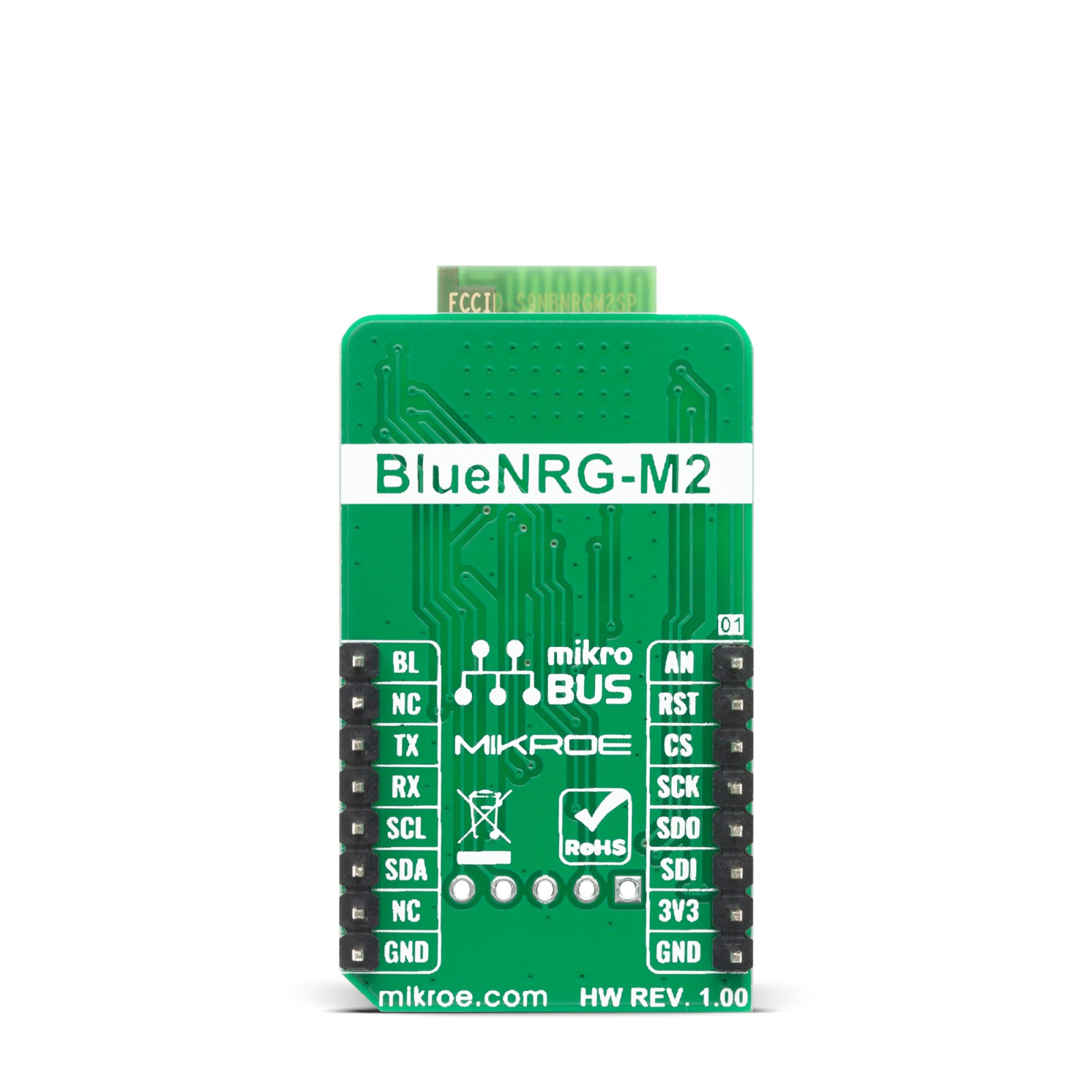
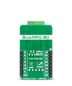
This table shows how the pinout on BLE 6 Click corresponds to the pinout on the mikroBUS™ socket (the latter shown in the two middle columns).
Onboard settings and indicators
Label | Name | Default | Description |
---|---|---|---|
LD1 | PWR | – | Power LED Indicator |
LD2 | DIO14 | – | User Configurable LED |
JP1, JP2 | MODE SEL | Left | SPI Mode Selection: left position for Slave, right position for Master |
T1 | BOOT | – | Bootloader activation button |
Software Support
We provide a library for the BLE 6 Click on our LibStock page, as well as a demo application (example), developed using MikroElektronika compilers. The demo can run on all the main MikroElektronika development boards.
Library Description
The library covers all the necessary functions to control BLE 6 click board. Library performs a standard UART interface communication.
Key functions:
uint8_t ble6_read_byte( void )
– Read Single Byte.void ble6_write_byte ( uint8_t input )
– Write Single Byte.void ble6_send_command ( uint8_t *tx_data, uint8_t n_bytes )
– Send command function.
Examples description
The application is composed of three sections :
- System Initialization – Initializes UART, sets RST, CS and PWM pin as outputs and begins to write a log.
- Application Initialization – Initialization driver enables – UART, sets handlers initialize and enable UART interrupt, reset and configures BLE module, initialize BLE Server Profile ( Services and Characteristics ).
- Application Task – (code snippet) This example demonstrates the use of the BLE 6 Click board. The app starts by checking the system ready flag and returns the Bluetooth device address. After that, the chain of commands creates Primary Server Profiles: Device Information, Generic Access and Custom Service to Start Advertising. For transmit messages, we use Generic Access Primary Service with Write permissions of the characteristic Element. In this example, transmitting message is limited to a maximum of 11 characters. Results are being sent to the Usart Terminal where you can track their changes.
void application_task ( ) { ble6_event_handler( ); while ( device_connected_flag ) { if ( ble6_strncmp( &rx_response[ 0 ],&hci_le_serverwrite_event[ 0 ], 1 ) == 0 ) { ble6_response_handler( ); } } }
Additional Functions :
void ble6_handler ( )
– Default handler.void ble6_connect_handler ( )
– Connect handler.void ble6_response_handler ( )
– Response handler.void ble6_event_handler ( )
– Event handler.void ble6_local_version_info ( )
– Display local version information.void ble6_fw_details ( )
– Display FW details.void ble6_le_meta_event ( )
– Meta event.void ble6_aci_gap_init ( )
– Display ACI GAP init. information.void ble6_display_log ( )
– Display log.ble6_module_init ( )
– Module initialization.
The full application code, and ready to use projects can be found on our LibStock page.
Other mikroE Libraries used in the example:
- UART
- Conversions
Additional notes and informations
Depending on the development board you are using, you may need USB UART click, USB UART 2 click or RS232 click to connect to your PC, for development systems with no UART to USB interface available on the board. The terminal available in all MikroElektronika compilers, or any other terminal application of your choice, can be used to read the message.
mikroSDK
This Click board™ is supported with mikroSDK – MikroElektronika Software Development Kit. To ensure proper operation of mikroSDK compliant Click board™ demo applications, mikroSDK should be downloaded from the LibStock and installed for the compiler you are using.
For more information about mikroSDK, visit the official page.