BLE 5 Click
R550.00 ex. VAT
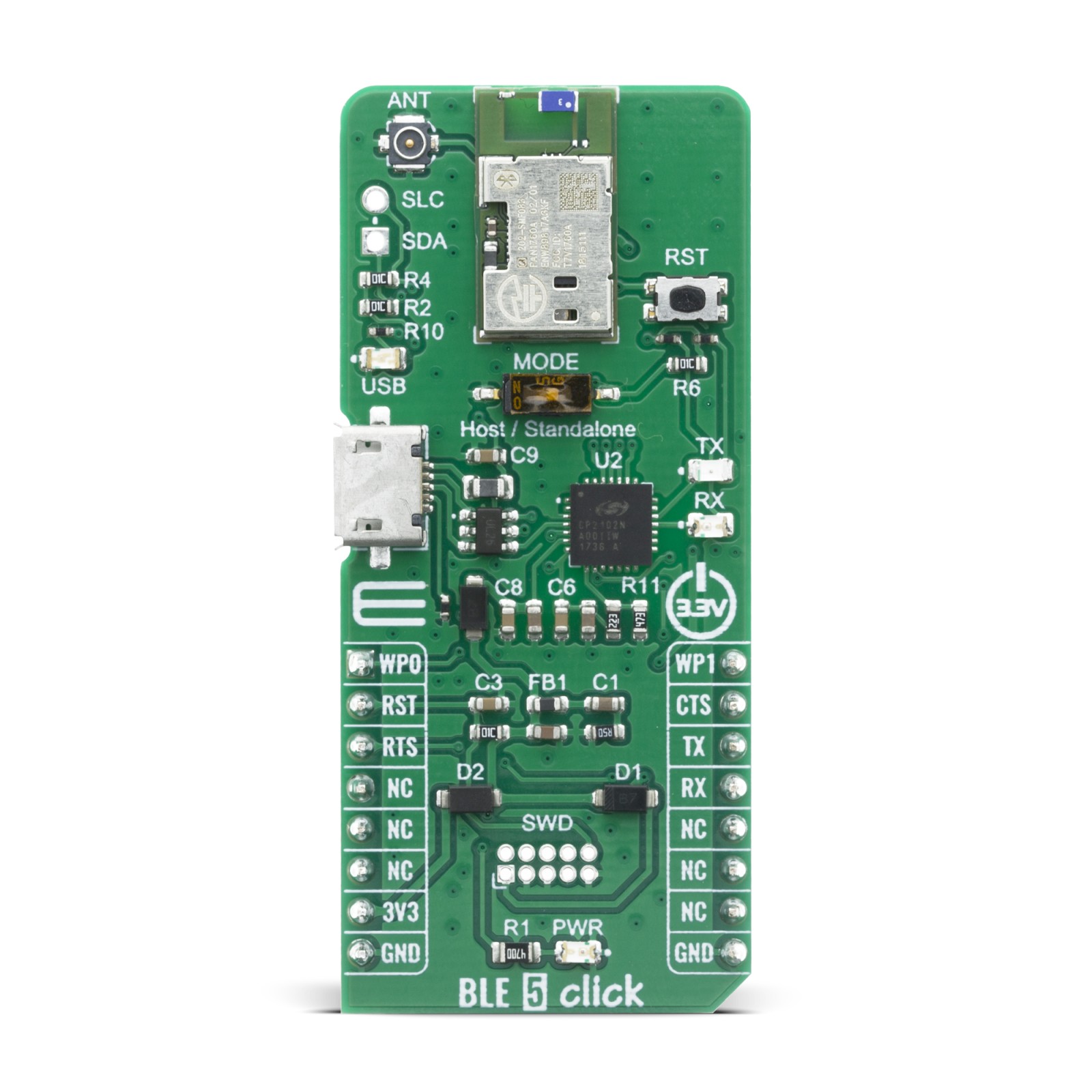
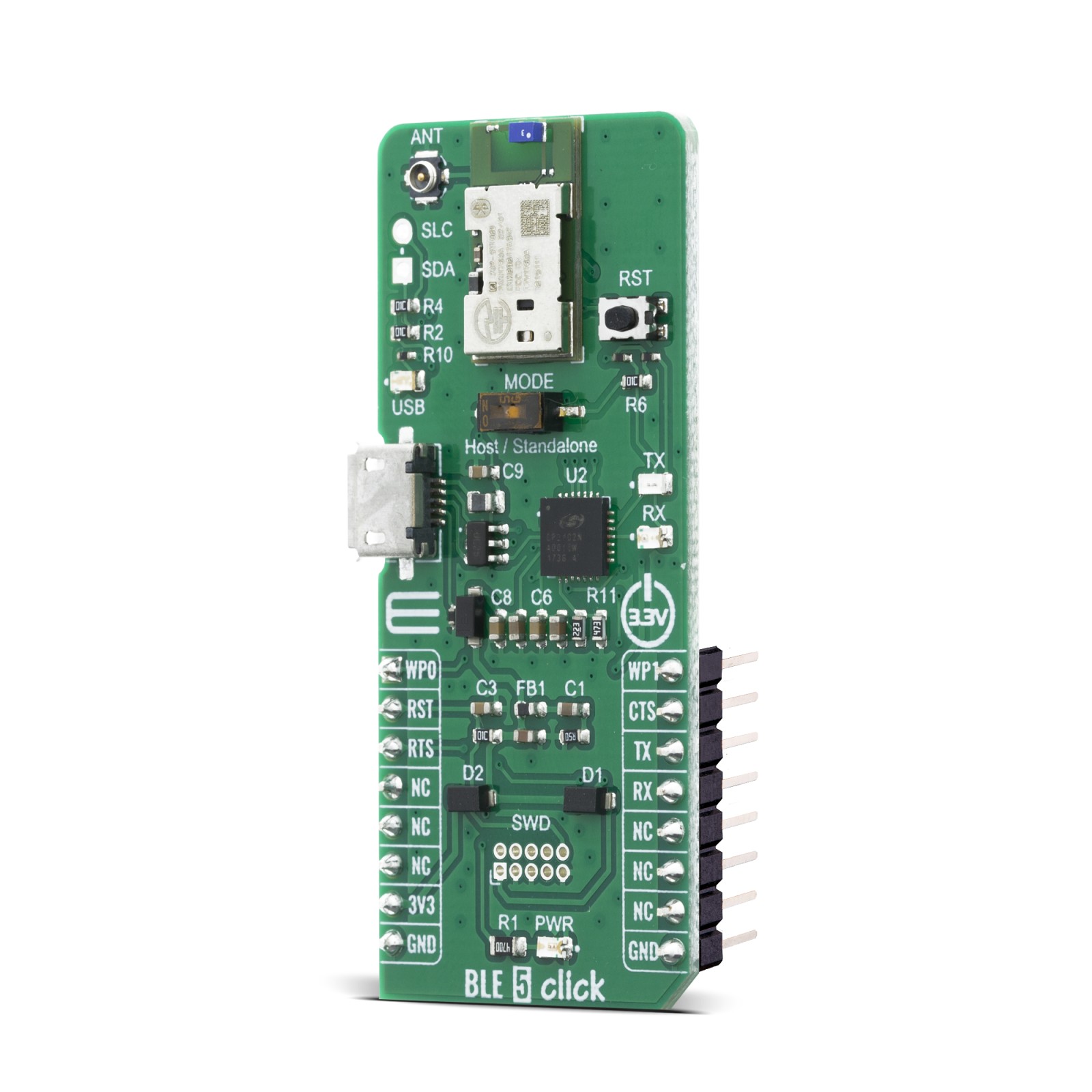
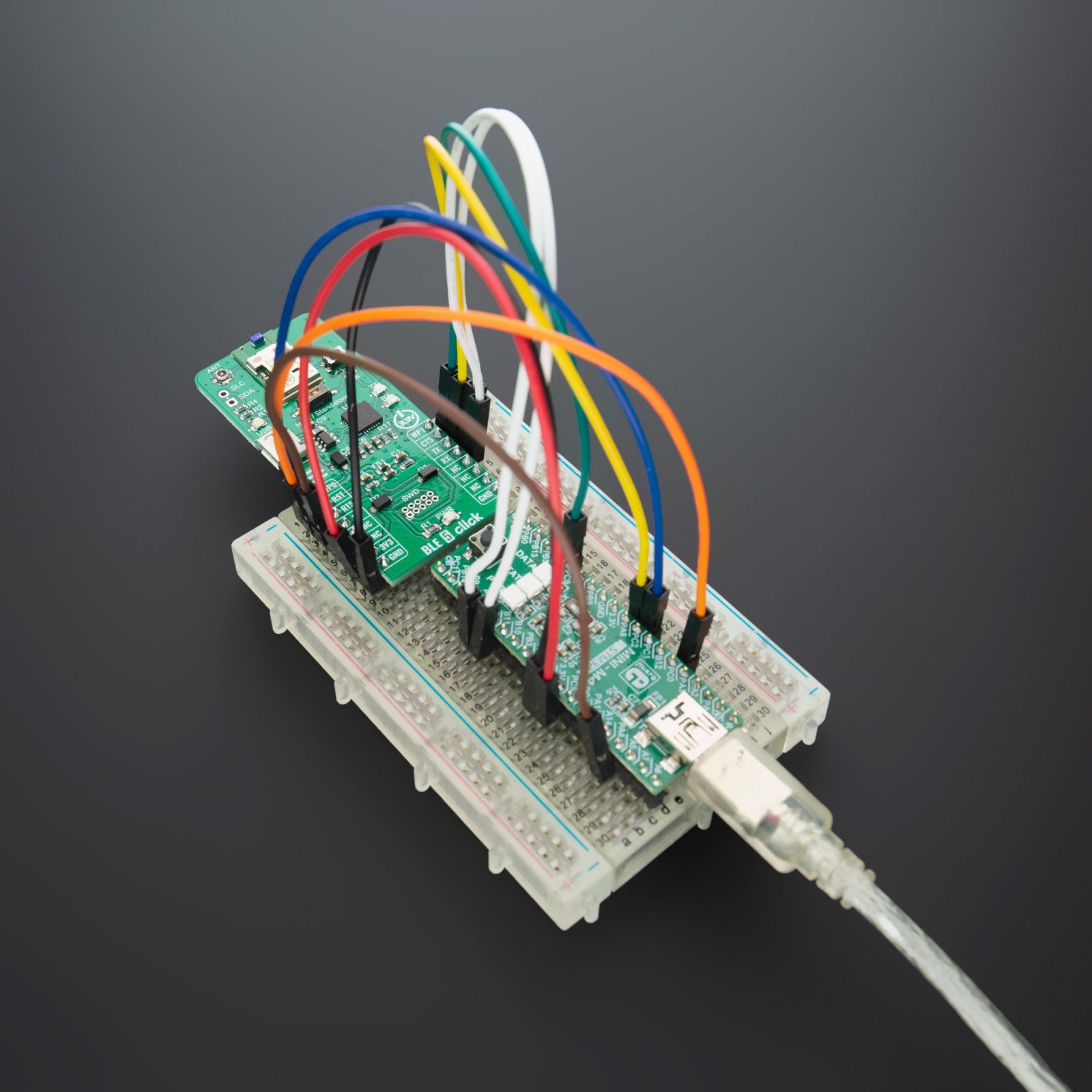
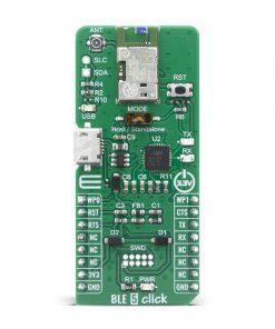
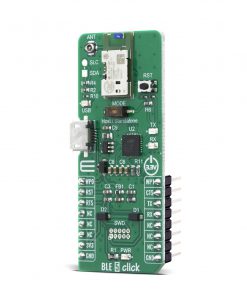
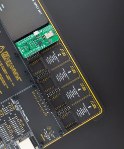
The BLE 5 Click is a Click board™ witch provide BT/BLE connectivity for any embedded application. BLE 5 click based on the PAN1760A, a module from Panasonic. The Click board™ with small Bluetooth Low Energy module for easy integration of Bluetooth Low Energy connectivity (BLE) into various electronic devices. Our board is coming with module already pre programmed for AT command mode and can be controlled over UART interface, in case you need this module to work in Host or Stand-Alone mode a new firmware needs to be applied. Given its features, this click can be used for health, sports, and wellness devices as well as Industrial, home, and building automation; and smart phone, tablet, and PC accessories.
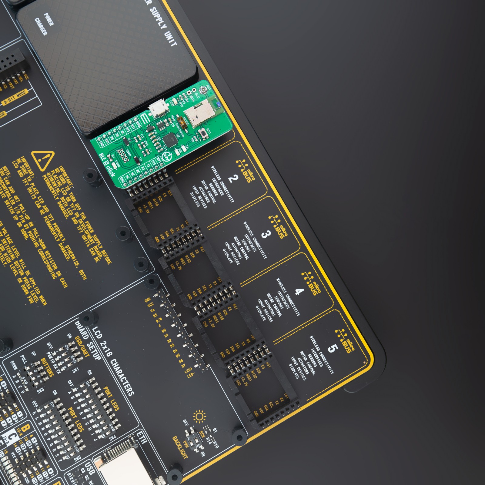
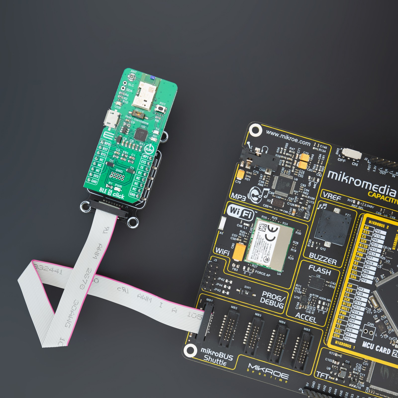
BLE 5 Click is supported by a mikroSDK compliant library, which includes functions that simplify software development. This Click board™ comes as a fully tested product, ready to be used on a system equipped with the mikroBUS™ socket.
Stock: Lead-time applicable.
| 5+ | R522.50 |
| 10+ | R495.00 |
| 15+ | R467.50 |
| 20+ | R449.90 |
NOTE: Enhance your connectivity options with our WiFi Active FPC Antenna, designed to integrate with this Click board™ seamlessly. Unlock the true potential of wireless connectivity in your projects using this high-performance antenna, currently available in our offer.
How does it work?
The BLE 5 Click is a Click board™ based on the PAN1760A, a module from Panasonic that has some impressive features including the fact that it is Bluetooth 4.2 low energy support with ARM Cortex-M0 processor with Single Wire Debug (SWI) interface. The Click board™ can either be operated in AT-Command or Host mode for very simple integration of Bluetooth connectivity into existing products, or in Stand-Alone mode.

The BLE 5 Click in AT-Command or Host mode Click board™ Besides the commonly used UART RX, TX, RTS, and CTS, BLE 5 Click has also WP0 and WP1 pins, which are routed to the PWM and AN pins of the mikroBUS™ socket, respectively. The PAN1760A modul contains internal antenna with receiver sensitivity -93 dBm, and the BLE 5 click board also features an SMA connector so it can be equipped with the appropriate 2.4 GHz antenna.
The Click board™ Stand-Alone mode, with 256 kB flash memory and 83 kB RAM for user application, the BLE 5 click can be used for many applications without the need for an external processor, saving cost, complexity, and space. Peak power consumption of only 3.6 mA in Tx and Rx mode allows advanced wireless functionalities in IoT, medical, and industrial applications without compromising battery life.
The BLE 5 click is equipped with the USB – micro B connector. It allows the module to be powered and configured by a personal computer. The CP2102N IC is a highly integrated USB to UART interface, from Silicon Labs. This IC adds USB to UART communication for embedded applications, registering itself as the virtual COM port, once the required drivers are installed. Besides the highly integrated USB to UART interface IC, this Click board™ is equipped with the additional ESD protection for the USB port, as well as the required signalization LEDs (RX, TX, power LED).
The BLE 5 click is equipped with the I2C master header, the PAN1760A modul contain I2C bus master interface. The I2C interface can operate is 3.3V, cannot operate at different voltage from ones other interfaces are operate at. This pins can be used for connecting external I2C peripherals such as sensors to the module.
This Click Board™ is designed to be operated only with 3.3V logic level. A proper logic voltage level conversion should be performed before the Click board™ is used with MCUs with logic levels of 5V.
Specifications
Type
BT/BLE
Applications
Health, sports, and wellness devices as well as Industrial, home, and building automation; and smart phone, tablet, and PC accessories
On-board modules
PAN1760A , Bluetooth 4.2 low energy module from Panasonic
Key Features
Bluetooth 4.2 low energy compliant, integrated antenna, 83 kB RAM available for application
Interface
GPIO,UART,USB
Feature
No ClickID
Compatibility
mikroBUS™
Click board size
L (57.15 x 25.4 mm)
Input Voltage
3.3V
Pinout diagram
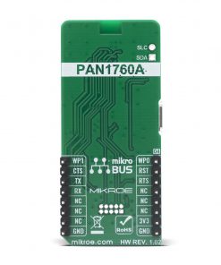
This table shows how the pinout on BLE 5 Click corresponds to the pinout on the mikroBUS™ socket (the latter shown in the two middle columns).
Onboard settings and indicators
| Label | Name | Default | Description |
|---|---|---|---|
| LD1 | PWR | – | Power LED Indicator |
| LD2 | TX | – | TX LED Indicator |
| LD3 | RX | – | RX LED Indicator |
| LD4 | USB | – | USB LED Indicator |
| RST | MODE | Left | PAN1760A Mode selector: Left position Host, Right position Standalone |
Software Support
We provide a library for the BLE 5 Click on our LibStock page, as well as a demo application (example), developed using MikroElektronika compilers. The demo can run on all the main MikroElektronika development boards.
Library Description
The library covers all the necessary functions to control BLE 5 Click board. A library performs the communication with the PAN1760 Series Bluetooth Low Energy RF Module via UART interface.
Key functions:
void ble5_device_reset ( void )– Device reset function.void ble5_send_at_command ( uint8_t *at_command, uint32_t at_command_length )– Send AT command function.
Examples description
The application is composed of three sections :
- System Initialization – Initializes UART, sets INT pin as input and AN, RST, CS and PWM pin as outputs and begins to write log.
- Application Initialization – Initialization driver enables – UART, sets handlers, initializes and enables UART interrupt, reset and configures BLE module, initialize BLE Server Profile ( Services and Characteristics ).
- Application Task – (code snippet) This example demonstrates the use of BLE 5 Click board. The app starts by checking system ready flag and returns Bluetooth device address. After that, the chain of commands creates Primary Server Profiles: Device Information, Generic Access and Custom Service to Start Advertising. For transmit and receive messages, we use Generic Access Primary Service with Read and Write permissions of the characteristic Element. Read: Message has been received, alias name value: “mikroE”. Write: A transmit message ( the maximum 15 characters ). Results are being sent to the Usart Terminal where you can track their changes.
Note: For communication with BLE 5 click use the android application on the link: https://play.google.com/store/apps/details?id=com.macdom.ble.blescanner
void application_task ( )
{
    if ( ble5_response_ready( ) == 1 )
    {
        ble5_process( );

        if ( msg_flg == 1 )
        {
            msg_flg = 0;
        }
    }

    if ( device_disconnected_flag == 1 )
    {
        ble5_start_advertising ( );

        device_disconnected_flag = 0;
    }

    if ( serverread_flag == 1 )
    {
        ble5_upd_val( serverread_profile, serverread_characteristic, serverread_element );
        while ( ble5_response_ready( ) == 0 );
        ble5_process( );

        if ( msg_flg == 1 )
        {
            msg_flg = 0;
        }

        ble5_accept_rx_val( serverread_profile, serverread_characteristic, serverread_element );
        while ( ble5_response_ready( ) == 0 );
        ble5_process( );

        if ( msg_flg == 1 )
        {
            msg_flg = 0;
        }

        serverread_flag = 0;
    }

    if ( serverwrite_flag == 1 )
    {
        ble5_send_request_to_write( );
        while ( ble5_response_ready( ) == 0 );
        ble5_process( );

        if ( msg_flg == 1 )
        {
            msg_flg = 0;
        }

        serverwrite_flag = 0;
    }
}
Other mikroE Libraries used in the example:
ble5_check_ok– Check ok response.ble5_default_handler– Default handler.ble5_event_handler– Event handler.ble5_error_handler– Error handler.ble5_check_sys_rdy– Checks is system ready.ble5_check_sw_ver– Checks software version.ble5_log_bt_addr– Log Bluetooth device address.ble5_upd_val– Updates the value of the given characteristic or descriptor.ble5_accept_rx_val– Accepting and updating the value to database.ble5_send_request_to_write– Sends request to write a char. or descriptor.ble5_start_advertising– Start advertising.ble5_create_service– Chain of commands creates Primary Server Profiles.ble5_add_service– Add Server characteristic.
The full application code, and ready to use projects can be found on our LibStock page.
Other mikroE Libraries used in the example:
- UART
- Conversions
Additional notes and informations
Depending on the development board you are using, you may need USB UART click, USB UART 2 click or RS232 click to connect to your PC, for development systems with no UART to USB interface available on the board. The terminal available in all MikroElektronika compilers, or any other terminal application of your choice, can be used to read the message.
mikroSDK
This Click board™ is supported with mikroSDK – MikroElektronika Software Development Kit. To ensure proper operation of mikroSDK compliant Click board™ demo applications, mikroSDK should be downloaded from the LibStock and installed for the compiler you are using.
For more information about mikroSDK, visit the official page.
Resources
Downloads
| Weight | 20 g |
|---|---|
| Brand | MikroElektronika |

