How does it work?
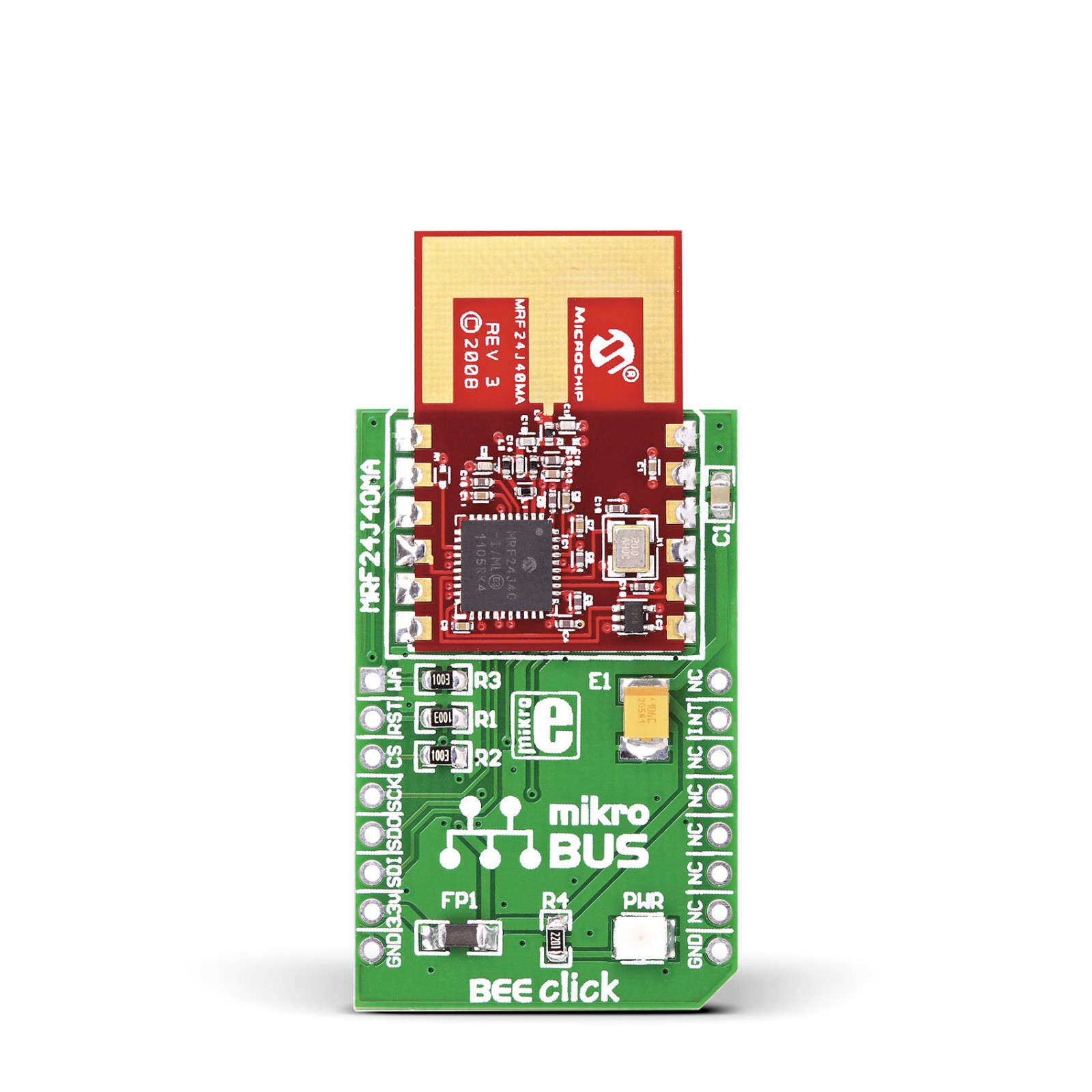
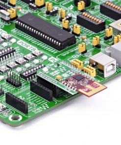
BEE Click is based on the MRF24J40MA, a 2.4GHz RF transceiver module from Microchip. It operates at ISM Band from 2.405 to 2.48GHz over an integrated PCB antenna and matching circuitry. You can set one of the 16 channels in the frequency range. With up to 36dB of TX power control range, it can achieve data rates of up to 250Kbps. The module integrates the PHY and MAC functionality and can create a low-cost, low-power, and low-data-rate Wireless Personal Area Network (WPAN). To reduce the load on the host MCU, the module features automatic packet retransmission, automatic acknowledgment, energy detection, CSMA-CA algorithm, three CCA modes, security encryption and decryption, and more.
To communicate with the host MCU, the BEE Click uses a standard 4-Wire SPI serial interface and supports SPI mode 0 only, which requires that SCK idles in a low state. In addition, BEE Click features other functionalities, such as the RST pin for resetting the module with active Low. The WA pin is an external wake-up trigger disabled by default and should be enabled in the software. This pin is in conjunction with the sleep mode. In addition, the module can signal one of eight interrupt events over the INT pin.
This Click board™ can only be operated with a 3.3V logic voltage level. The board must perform appropriate logic voltage level conversion before using MCUs with different logic levels. However, the Click board™ comes equipped with a library containing functions and an example code that can be used, as a reference, for further development.
Specifications
Type
ZigBee
Applications
Can be used for the development of ZigBee smart energy applications, wireless alarms and security, remote monitoring, and other electronic applications that need wireless communication
On-board modules
MRF24J40MA – 2.4GHz RF transceiver module from Microchip
Key Features
IEEE 802.15.4 compliant RF transceiver, supports ZigBee, MiWi, MiWi P2P, and proprietary wireless networking protocols, high receiver, and RSSI dynamic range, hardware CSMA-CA mechanism, automatic ACK response and FCS check, and more
Interface
GPIO,SPI
Feature
No ClickID
Compatibility
mikroBUS™
Click board size
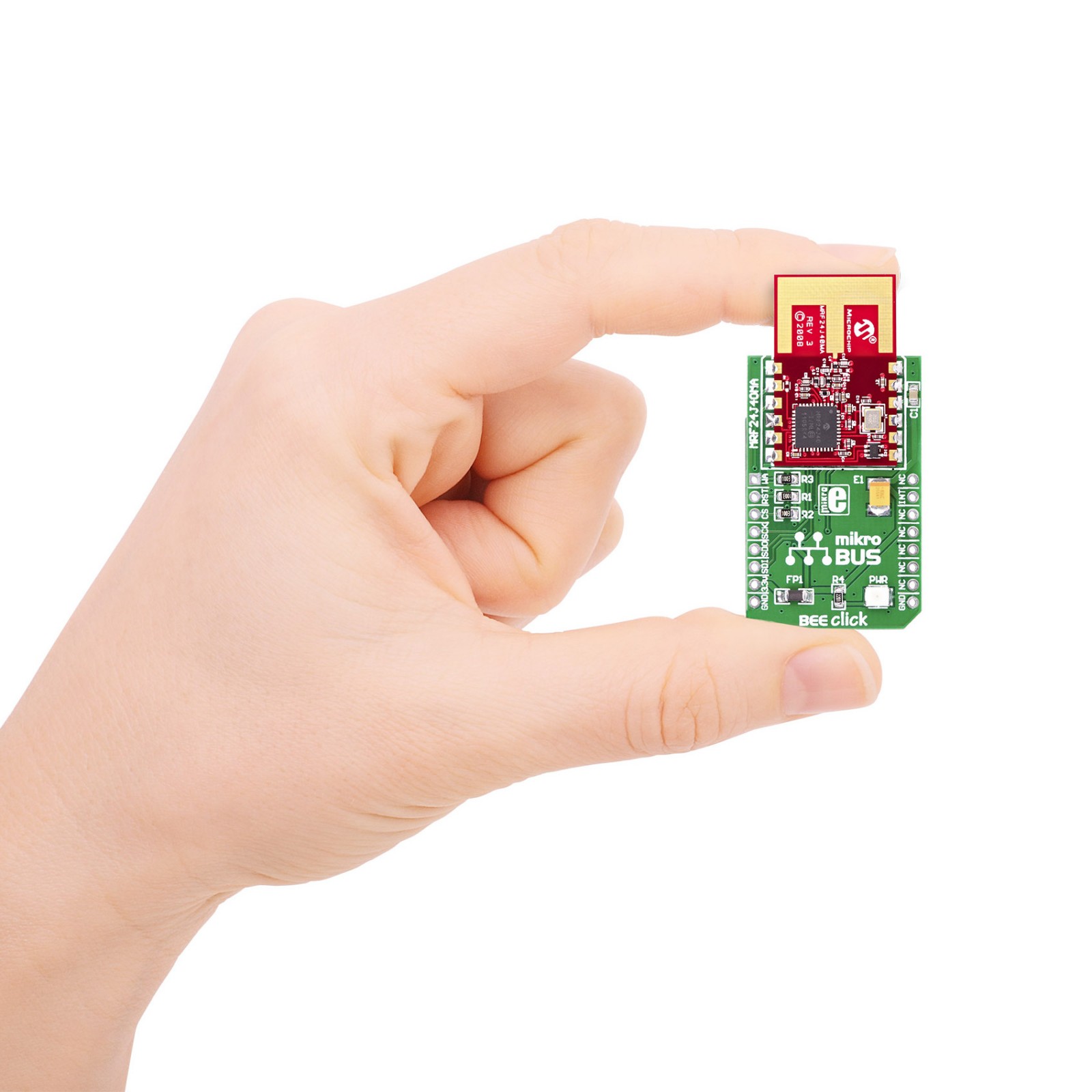
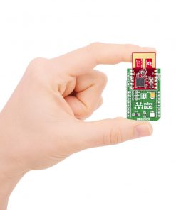
M (42.9 x 25.4 mm)
Input Voltage
3.3V
Pinout diagram
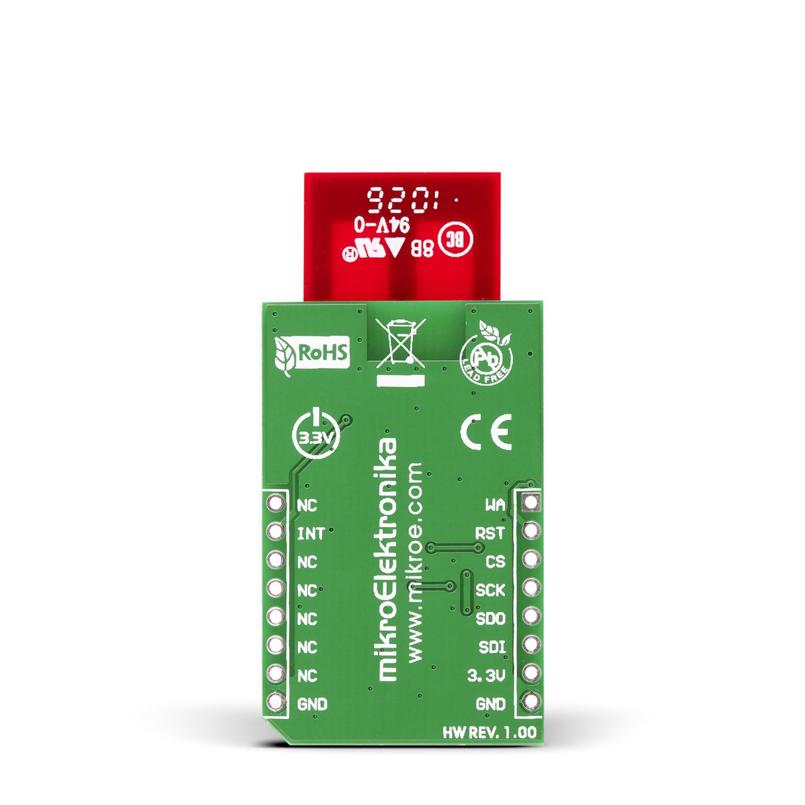
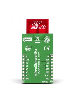
This table shows how the pinout on BEE Click corresponds to the pinout on the mikroBUS™ socket (the latter shown in the two middle columns).
Onboard settings and indicators
Label | Name | Default | Description |
---|---|---|---|
LD1 | PWR | – | Power LED Indicator |
BEE Click electrical specifications
Description | Min | Typ | Max | Unit |
---|---|---|---|---|
Supply Voltage | – | 3.3 | – | V |
Frequency Range | 2405 | – | 2480 | MHz |
Data Rate | – | – | 250 | Kbps |
Distance Range | – | – | 120 | m |
Sensitivity | – | -94 | – | dBm |
Software Support
We provide a library for the BEE Click as well as a demo application (example), developed using MIKROE compilers. The demo can run on all the main MIKROE development boards.
Package can be downloaded/installed directly from NECTO Studio Package Manager (recommended), downloaded from our LibStock™ or found on Mikroe github account.
Library Description
This library contains API for BEE Click driver.
Key functions
-
Generic transfer function.
-
Write the byte of data to the short register address function
-
Read the byte of data from the short register address function
Example Description
The click is designed to run on 3.3V power supply only.
void application_task ( void )
{
#ifdef RECEIVER
// Receiver mode
bee_read_rx_fifo( &bee, &rx_data_fifo[ 0 ] );
if ( memcmp( &rx_data_fifo_old[ 0 ], &rx_data_fifo[ 0 ], BEE_DATA_LENGHT ) )
{
memcpy( &rx_data_fifo_old [ 0 ], &rx_data_fifo[ 0 ], BEE_DATA_LENGHT );
log_printf( &logger, " - Received data : " );
log_printf( &logger, "%.6s rn", rx_data_fifo );
Delay_ms( 1500 );
}
Delay_ms( 500 );
#endif
#ifdef TRANSMITTER
// Transmitter mode
memcpy( &tx_data_fifo[ 13 ], &data_tx1[ 0 ], BEE_DATA_LENGHT);
bee_write_tx_normal_fifo( &bee, 0, &tx_data_fifo[ 0 ] );
log_printf( &logger, " - Sent data : " );
log_printf( &logger, "%.6s rn", data_tx1 );
Delay_ms( 3000 );
memcpy( &tx_data_fifo[ 13 ], &data_tx2[ 0 ], BEE_DATA_LENGHT );
bee_write_tx_normal_fifo( &bee, 0, &tx_data_fifo[ 0 ] );
log_printf( &logger, " - Sent data : " );
log_printf( &logger, "%.6s rn", data_tx2 );
Delay_ms( 3000 );
#endif
}
The full application code, and ready to use projects can be installed directly from NECTO Studio Package Manager (recommended), downloaded from our LibStock™ or found on Mikroe github account.
Other Mikroe Libraries used in the example:
- MikroSDK.Board
- MikroSDK.Log
- Click.Bee
Additional notes and informations
Depending on the development board you are using, you may need USB UART click, USB UART 2 Click or RS232 Click to connect to your PC, for development systems with no UART to USB interface available on the board. UART terminal is available in all MIKROE compilers.
mikroSDK
This Click board™ is supported with mikroSDK – MIKROE Software Development Kit. To ensure proper operation of mikroSDK compliant Click board™ demo applications, mikroSDK should be downloaded from the LibStock and installed for the compiler you are using.
For more information about mikroSDK, visit the official page.