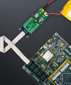
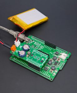
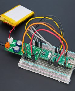
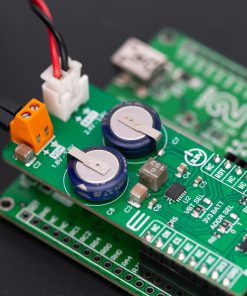
How does it work?
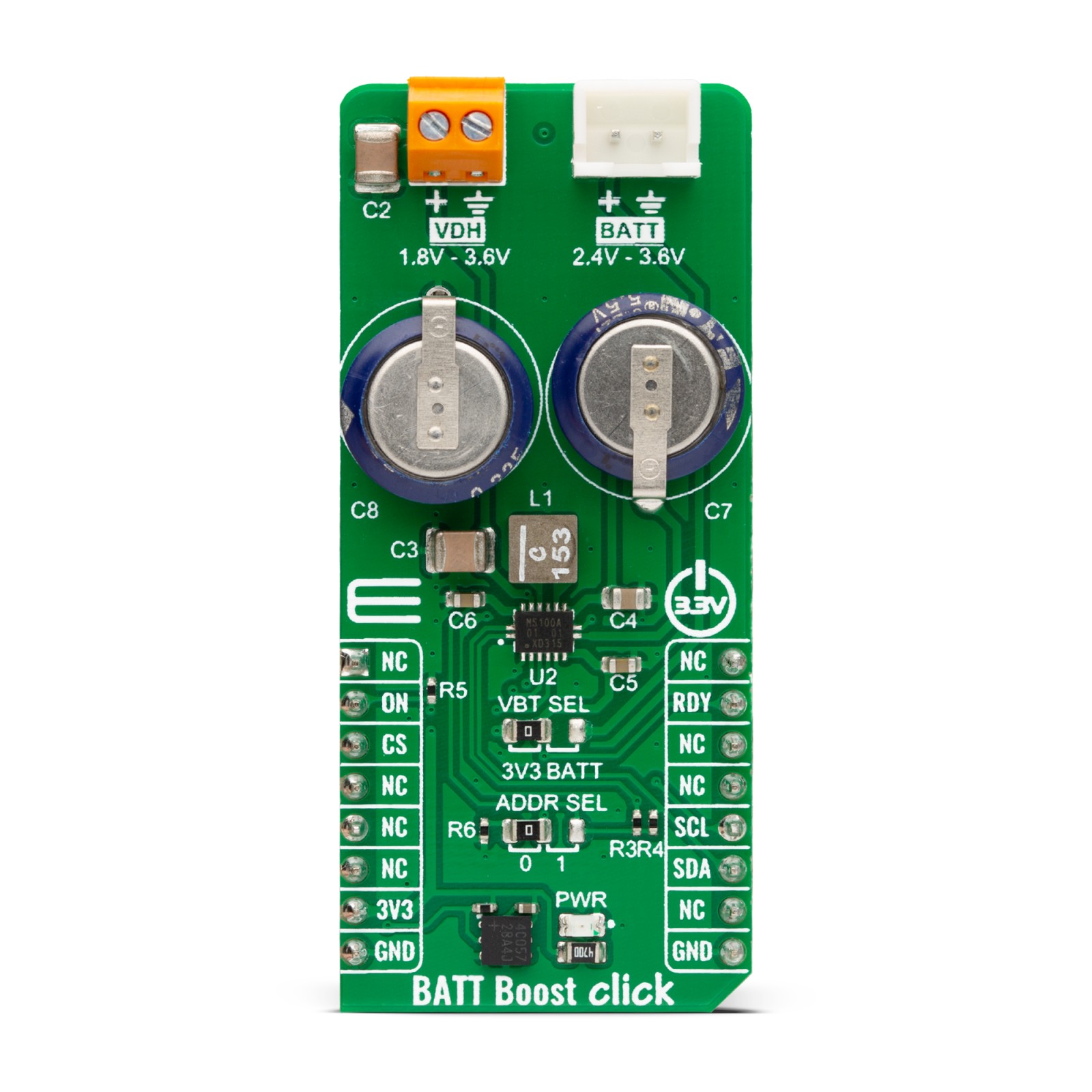
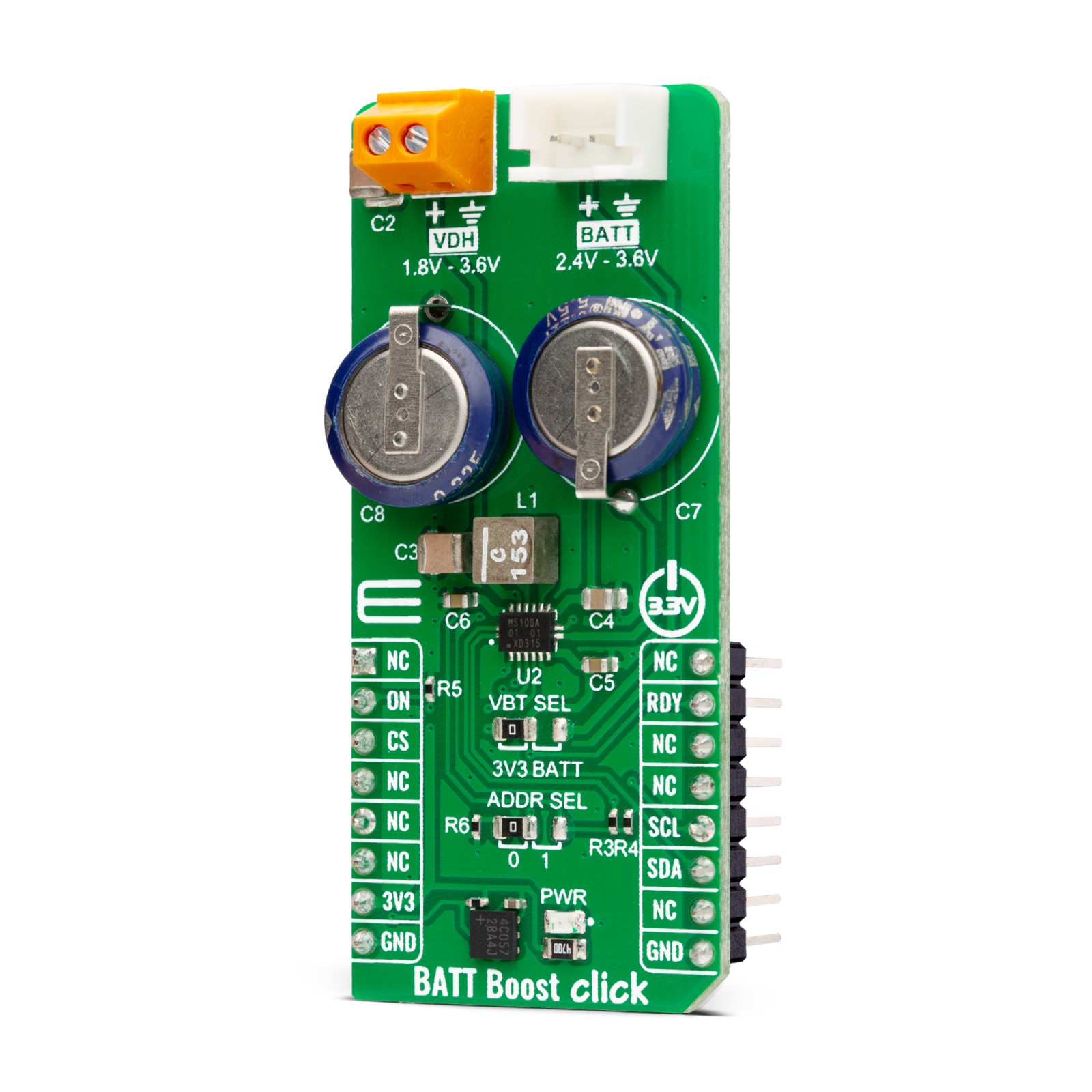
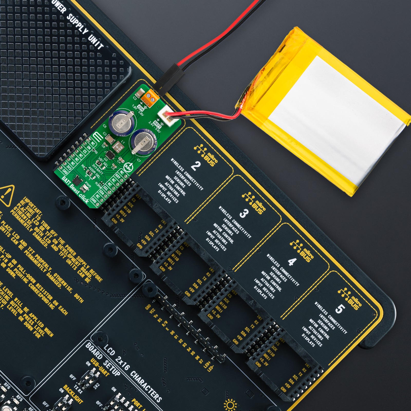
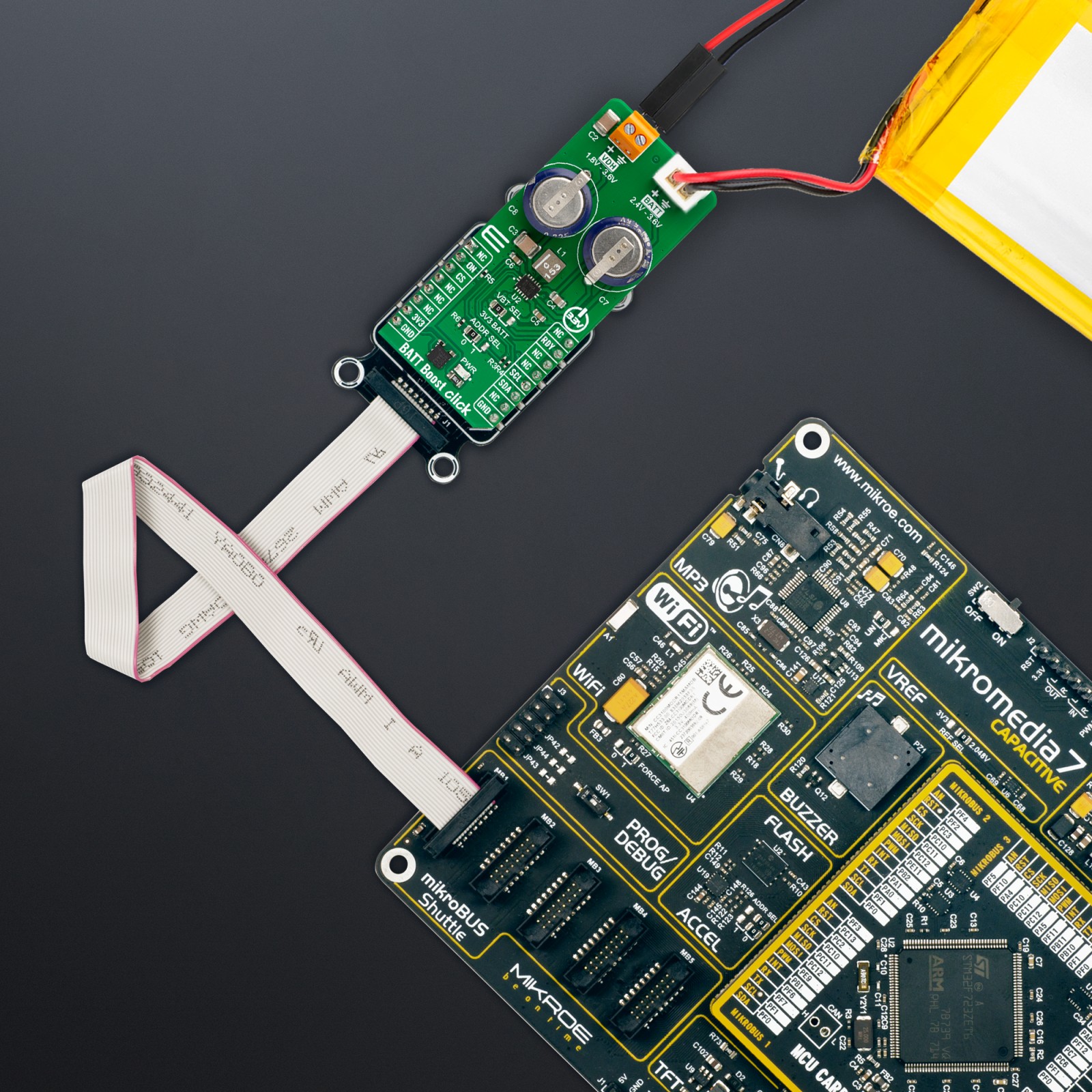
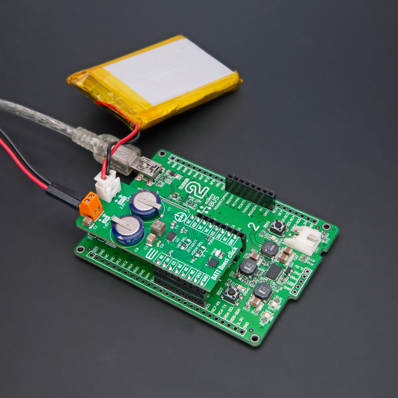
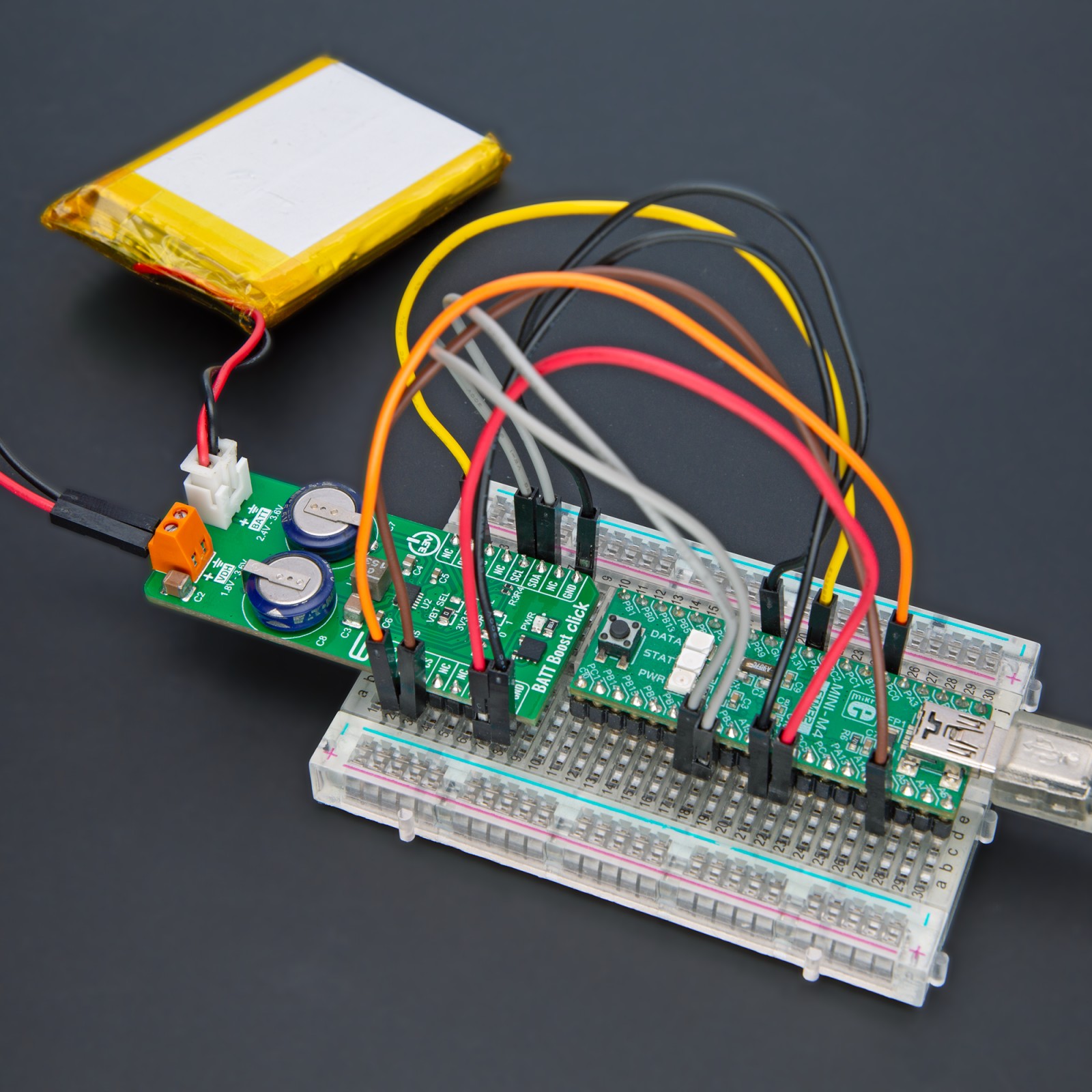
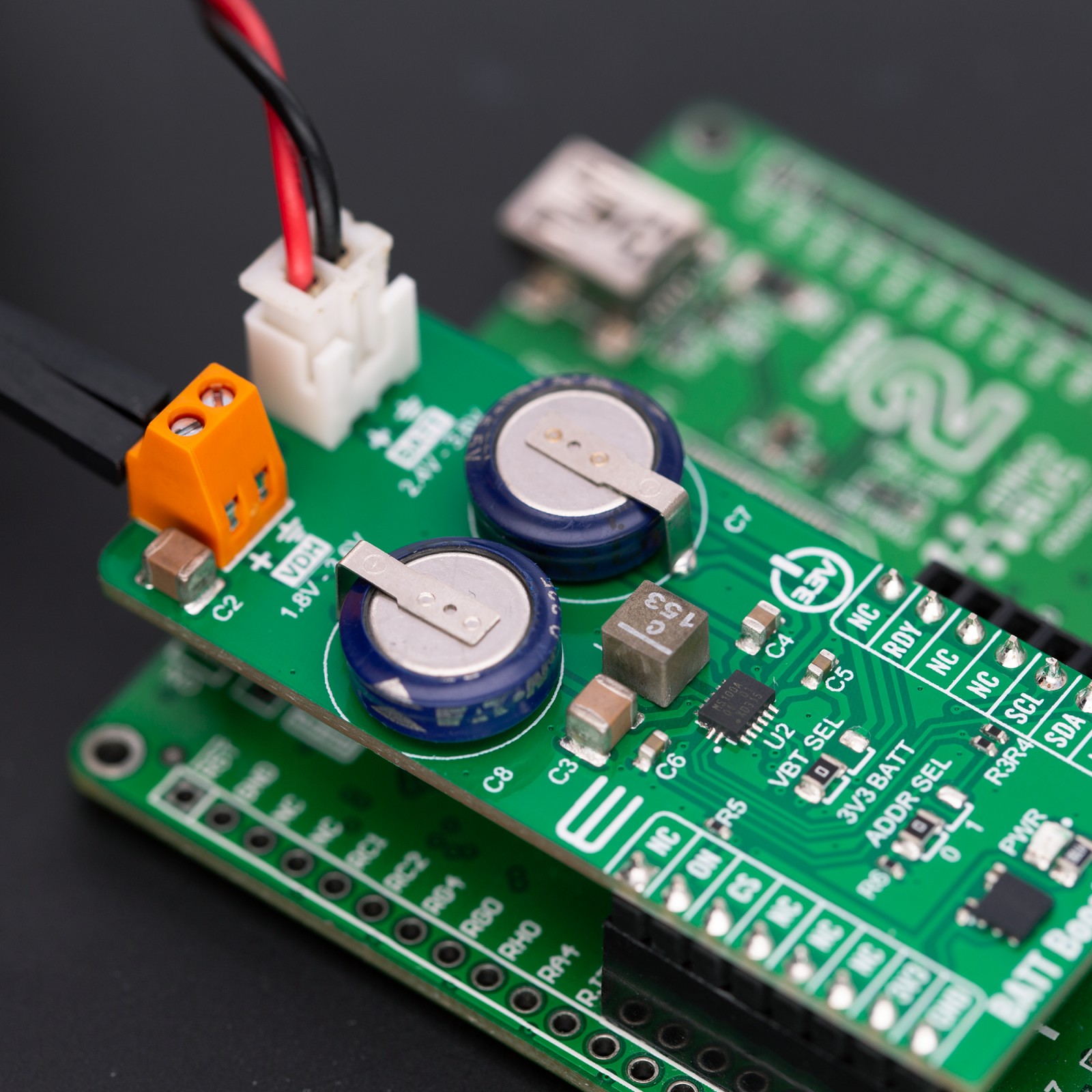
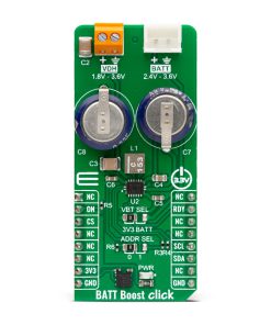
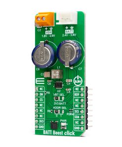
BATT Boost Click is based on the NBM5100A, a coin-cell battery life booster with adaptive power optimization from Nexperia. It contains an intelligent learning algorithm and two stages of high-efficiency DC-DC conversion. The first stage, DC-DC conversion, transfers energy from the lithium battery to a capacitive storage element at a low constant current. When charged, a second DC-DC conversion cycle utilizes this stored energy to supply a regulated voltage with high pulse load current capability on the VDH output terminal. The battery is never directly subjected to large load pulse currents, resulting in a longer, more predictable battery lifetime.
The NBM5100A has a programmable constant battery load current of 2mA up to 16mA. It also features an ultra-low standby current, integrated fuel gauge, high peak power efficiency, low pulse output current, protection against battery voltage dips, and more. The capacitor balancing IO of the NBM1500A is connected to two supercapacitors and is intended for applications utilizing series-connected supercapacitors requiring voltage balancing. The input supply source of the NBM5100A can be selected from the 3.3V rail of the mikroBUS™ socket or the coin battery itself. The selection can be made over the VBT SEL jumper.
BATT Boost Click uses a standard 2-wire I2C interface to communicate with the host MCU, supporting a clock frequency of up to 1MHz. The I2C address can be selected over the ADDR SEL jumper. The auto mode utilizes the start pin (ON) for one cycle. There are two ways to define the end of the active state in auto mode: short pulse on the ON pin and long pulse on the ON pin. The NBM1500A will interrupt the host MCU when it is ready over the RDY pin.
This Click board™ can be operated only with a 3.3V logic voltage level. The board must perform appropriate logic voltage level conversion before using MCUs with different logic levels. Also, it comes equipped with a library containing functions and an example code that can be used as a reference for further development.
Specifications
Type
Boost
Applications
Can be used for the development of battery-powered IoT, industrial, consumer and wearable devices, and more
On-board modules
NBM5100A – coin-cell battery life booster with adaptive power optimization from Nexperia
Key Features
Coin-cell battery life booster with adaptive power optimization, programmable constant battery load current, protection against battery voltage dips, low ripple regulated programmable output voltage, low standby current, high peak conversion efficiency, integrated fuel gauge, and more
Interface
I2C
Feature
ClickID
Compatibility
mikroBUS™
Click board size
L (57.15 x 25.4 mm)
Input Voltage
3.3V,External
Pinout diagram
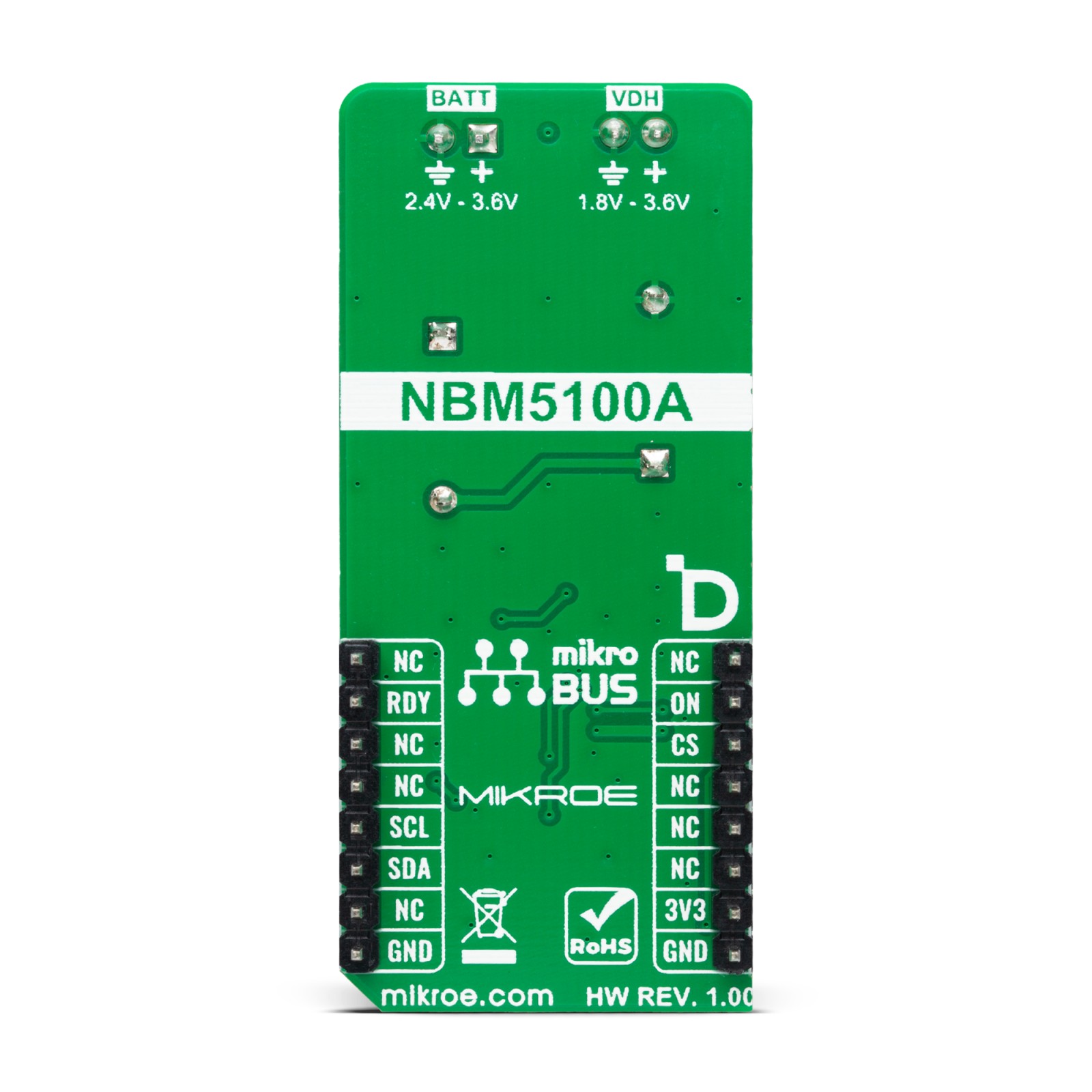
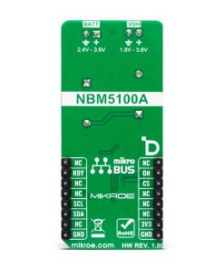
This table shows how the pinout on BATT Boost Click corresponds to the pinout on the mikroBUS™ socket (the latter shown in the two middle columns).
Onboard settings and indicators
Label | Name | Default | Description |
---|---|---|---|
LD1 | PWR | – | Power LED Indicator |
JP1 | ADDR SEL | Left | I2C Address Selection 0/1: Left position 0, Right position 1 |
JP2 | VBT SEL | Left | IC Input Supply Selection 3V3/BATT: Left position 3V3, Right position BATT |
BATT Boost Click electrical specifications
Description | Min | Typ | Max | Unit |
---|---|---|---|---|
Supply Voltage | – | 3.3 | – | V |
Battery Cell Supply Voltage | 2.4 | – | 3.6 | V |
Regulated Output Voltage | 1.8 | – | 3.6 | V |
Constant Battery Load Current | 2 | – | 16 | mA |
Software Support
We provide a library for the BATT Boost Click as well as a demo application (example), developed using MIKROE compilers. The demo can run on all the main MIKROE development boards.
Package can be downloaded/installed directly from NECTO Studio Package Manager(recommended), downloaded from our LibStock™ or found on Mikroe github account.
Library Description
This library contains API for BATT Boost Click driver.
Key functions
-
battboost_get_vcap
This function is used to read the storage capacitor voltage status. -
battboost_set_op_mode
This function is used to select the desired operating mode of the device. -
battboost_get_status
This function reads the the status information of low battery input, capacitor input voltage early warning, VDH output alarm and ready state.
Example Description
This library contains API for the BATT Boost Click driver. This driver provides the functions to controle battery energy management device designed to maximize usable capacity from non-rechargeable.
void application_task ( void )
{
float vcap = 0;
uint8_t status = 0;
uint32_t chenergy = 0;
if ( BATTBOOST_STATUS_READY != battboost_get_ready( &battboost ) )
{
if ( BATTBOOST_OK == battboost_set_op_mode( &battboost, BATTBOOST_OP_MODE_CHARGE ) )
{
log_printf( &logger, "nOperating state: Chargern" );
}
if ( BATTBOOST_OK == battboost_get_vcap( &battboost, &vcap ) )
{
log_printf( &logger, " Capacitor Voltage: %.2f V rn", vcap );
}
if ( BATTBOOST_OK == battboost_get_chenergy( &battboost, &chenergy ) )
{
log_printf( &logger, " Charge cycle count: %lu rn", chenergy );
}
Delay_ms( 1000 );
}
else
{
if ( BATTBOOST_OK == battboost_set_op_mode( &battboost, BATTBOOST_OP_MODE_ACTIVE ) )
{
log_printf( &logger, "nOperating state: Activern" );
if ( BATTBOOST_OK == battboost_get_vcap( &battboost, &vcap ) )
{
log_printf( &logger, " Capacitor Voltage: %.2f V rn", vcap );
}
if ( BATTBOOST_OK == battboost_get_status( &battboost, &status ) )
{
if ( BATTBOOST_STATUS_EW & status )
{
log_printf( &logger, " Status: Early warning.rn" );
}
if ( BATTBOOST_STATUS_ALRM & status )
{
log_printf( &logger, " Status: Low output voltage in the Active state.rn" );
}
}
}
Delay_ms( 1000 );
}
}
The full application code, and ready to use projects can be installed directly from NECTO Studio Package Manager(recommended), downloaded from our LibStock™ or found on Mikroe github account.
Other Mikroe Libraries used in the example:
- MikroSDK.Board
- MikroSDK.Log
- Click.BATTBoost
Additional notes and informations
Depending on the development board you are using, you may need USB UART click, USB UART 2 Click or RS232 Click to connect to your PC, for development systems with no UART to USB interface available on the board. UART terminal is available in all MIKROE compilers.
mikroSDK
This Click board™ is supported with mikroSDK – MIKROE Software Development Kit. To ensure proper operation of mikroSDK compliant Click board™ demo applications, mikroSDK should be downloaded from the LibStock and installed for the compiler you are using.
For more information about mikroSDK, visit the official page.