BATT Boost 2 Click
R510.00 ex. VAT
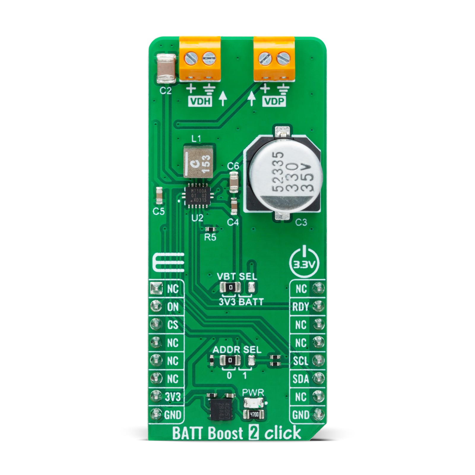
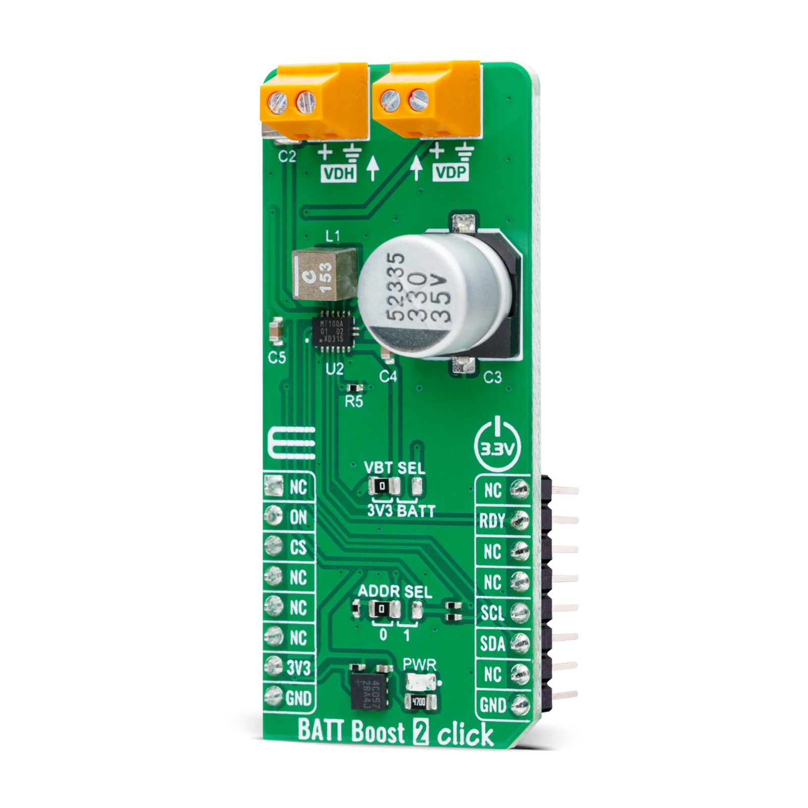
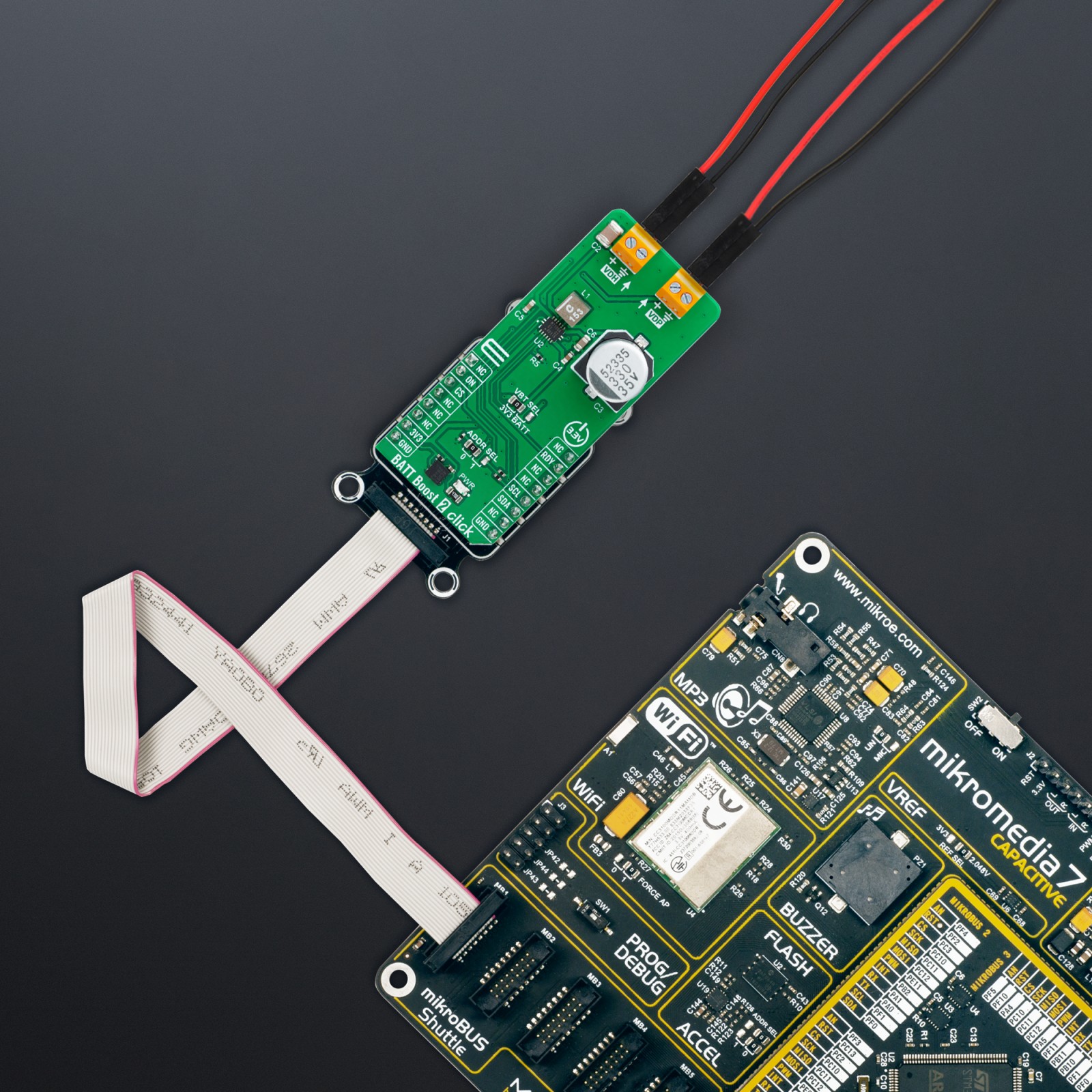
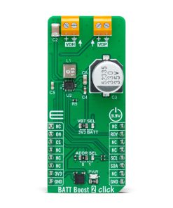
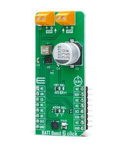
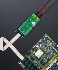
BATT Boost 2 Click is a compact add-on board designed to extend the battery life of non-rechargeable, primary batteries in low-voltage, low-power applications. This board features the NBM7100A, a coin-cell battery-life booster with adaptive power optimization from Nexperia. The NBM7100A integrates two high-efficiency DC-DC conversion stages and an intelligent learning algorithm to optimize energy usage, allowing it to handle bursts of current up to 200mA without depleting the battery. It features two output terminals: VDH for high pulse load applications and VDP for powering ‘Always-ON’ components. Communication with the host MCU is achieved via the I2C interface, supporting up to 1MHz clock frequencies. BATT Boost 2 Click is ideal for powering wireless IoT sensors, industrial devices, and wearable consumer electronics that require efficient power management and frequent bursts of energy.
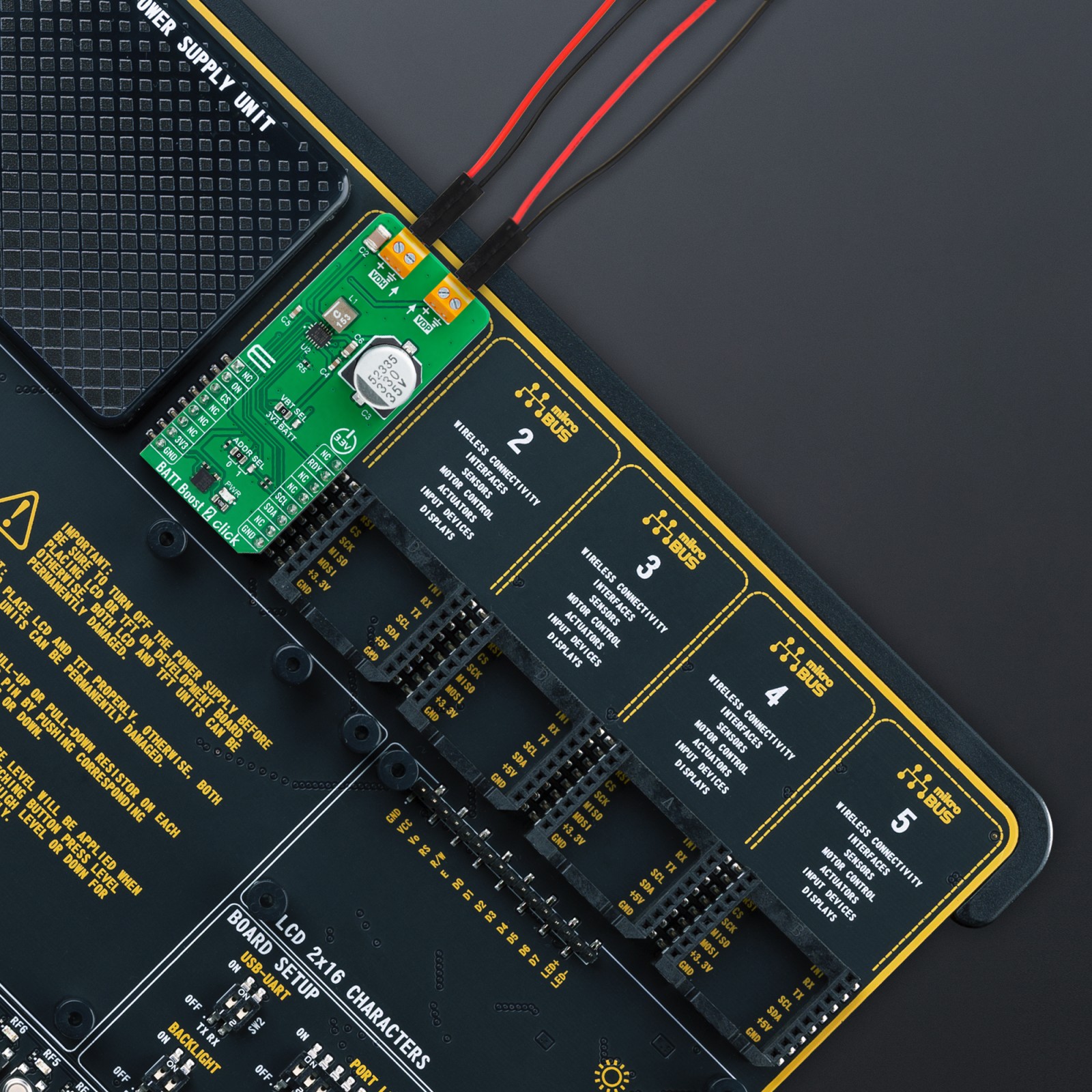
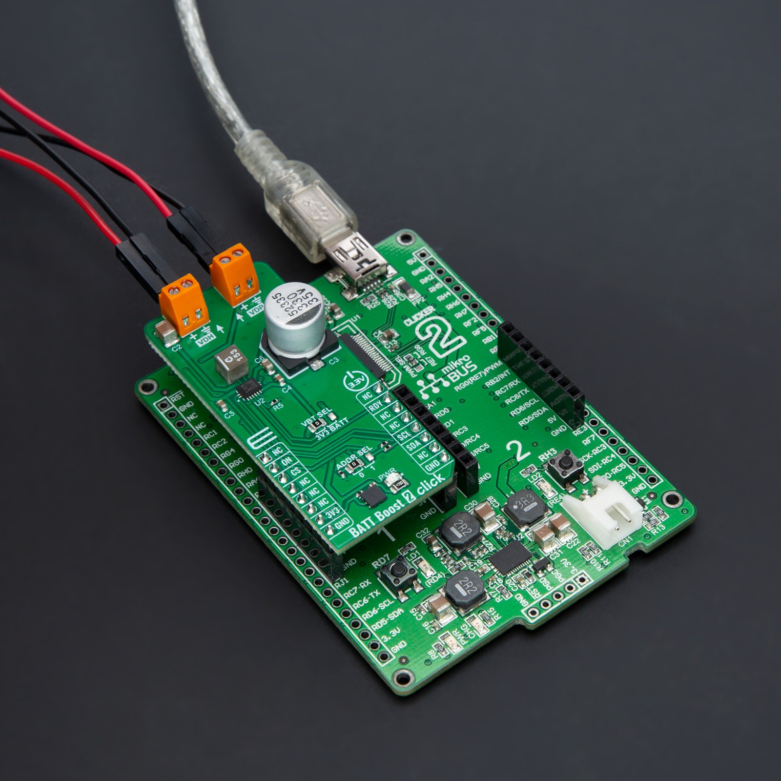
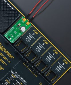
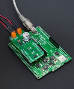
BATT Boost 2 Click is fully compatible with the mikroBUS™ socket and can be used on any host system supporting the mikroBUS™ standard. It comes with the mikroSDK open-source libraries, offering unparalleled flexibility for evaluation and customization. What sets this Click board™ apart is the groundbreaking ClickID feature, enabling your host system to seamlessly and automatically detect and identify this add-on board.
Stock: Lead-time applicable.
| 5+ | R484.50 |
| 10+ | R459.00 |
| 15+ | R433.50 |
| 20+ | R417.18 |
How does it work?
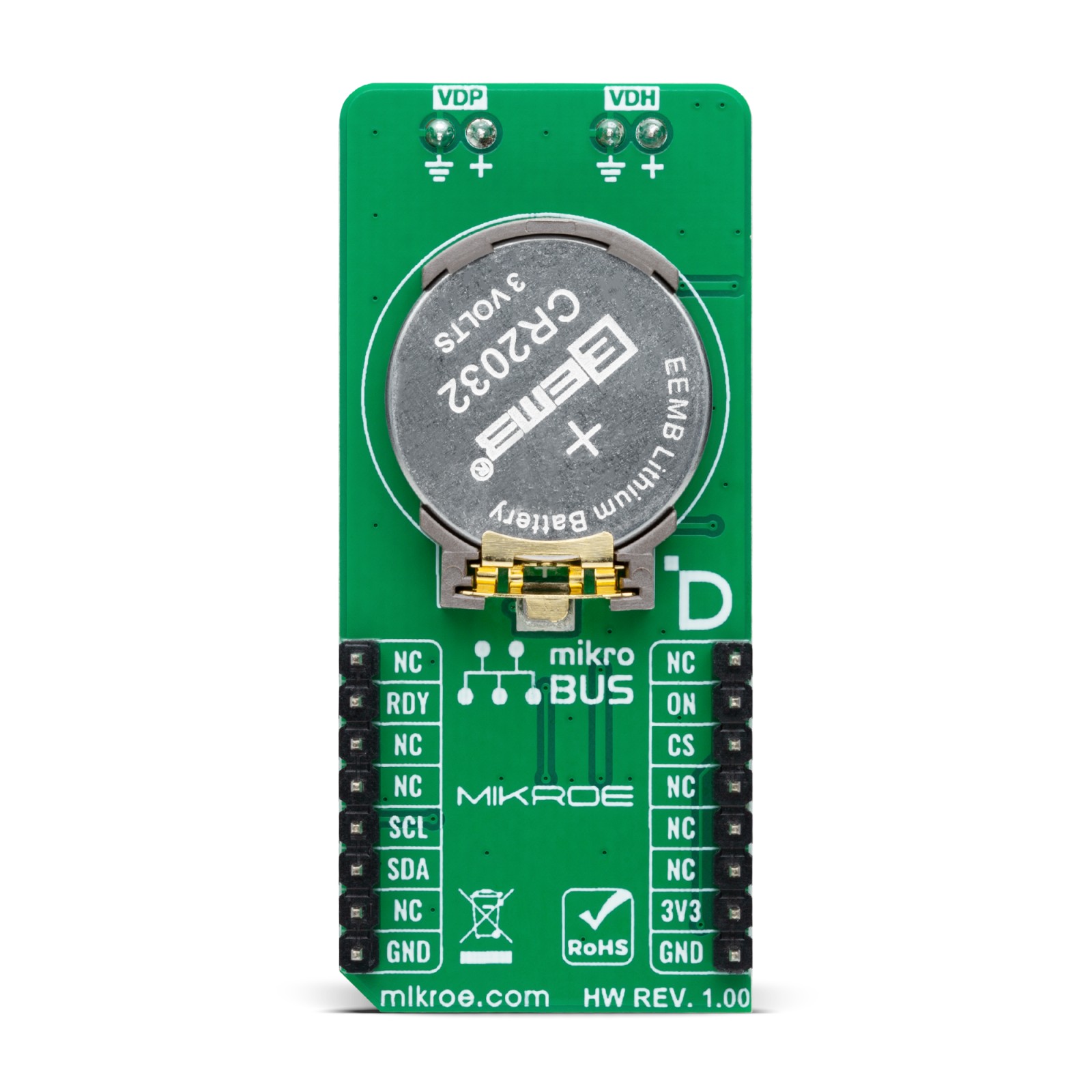
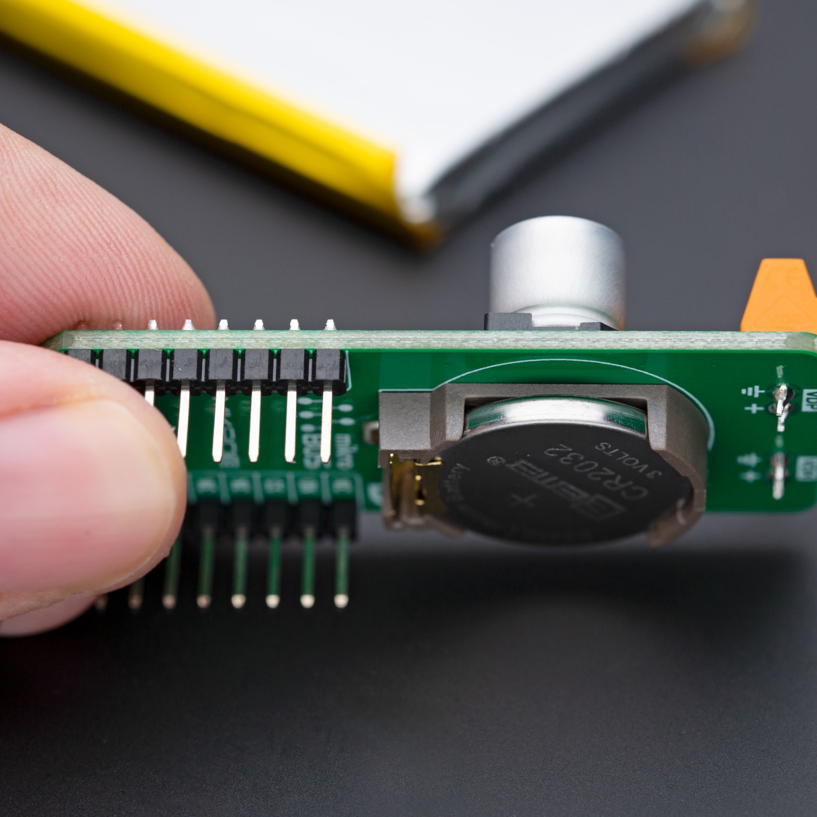
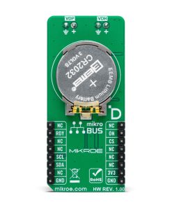
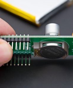
BATT Boost 2 Click is based on the NBM7100A, a coin-cell battery-life booster with adaptive power optimization from Nexperia, designed to extend the battery life of non-rechargeable, primary batteries in low-voltage, low-power applications. This innovative solution is specifically designed to address the voltage drops and battery life limitations typically associated with high pulse current demands from primary batteries like the CR2032 coin cell attached to the back of the board. The NBM7100A’s adaptive learning algorithm monitors the system’s energy consumption and optimizes the internal DC-DC conversion process to manage the remaining charge in the storage capacitor efficiently, reducing energy waste. This makes BATT Boost 2 Click ideal for powering wireless IoT sensors, industrial devices, and wearable consumer electronics where efficient battery usage is crucial, especially in applications with high internal battery impedance and frequent bursts of power demand.

As mentioned, the NBM7100A integrates two high-efficiency DC-DC conversion stages and employs an intelligent learning algorithm to maximize the usable capacity of primary batteries. The first stage draws energy at a low, steady current from the battery and stores it in a capacitor. This stored energy is then released during the second stage of DC-DC conversion to supply a stable, regulated voltage with high pulse load capability on the VDH output terminal. This design allows the device to handle bursts of current, up to 200mA, without directly taxing the battery with large pulse currents, ensuring a longer, more predictable battery lifespan.
In addition to the VDH terminal, BATT Boost 2 Click features another output labeled VDP, which serves as a ‘permanent’ supply terminal with a maximum output current of 5mA. The VDP terminal is ideal for powering ‘Always-ON’ system components, such as the core and I/O of a host MCU. On the power supply side, the main power supply for the NBM7100A can be sourced either from the 3.3V mikroBUS™ socket or the attached coin battery on the back of the board, with the selection made via the VBAT SEL jumper.
The NBM7100A offers three distinct operating modes: Continuous, On-demand, and Auto mode. Continuous mode suits applications requiring immediate pulse load capability, ensuring the system can respond quickly to power demands. On-demand mode, on the other hand, is optimized for extending battery life in low-duty cycle applications, where the system remains in sleep mode for extended periods. Auto mode automates the process of managing power transitions between charging and active states without requiring constant oversight from the serial bus, using a HIGH logic level from the ON pin on the mikroBUS™ socket for control.
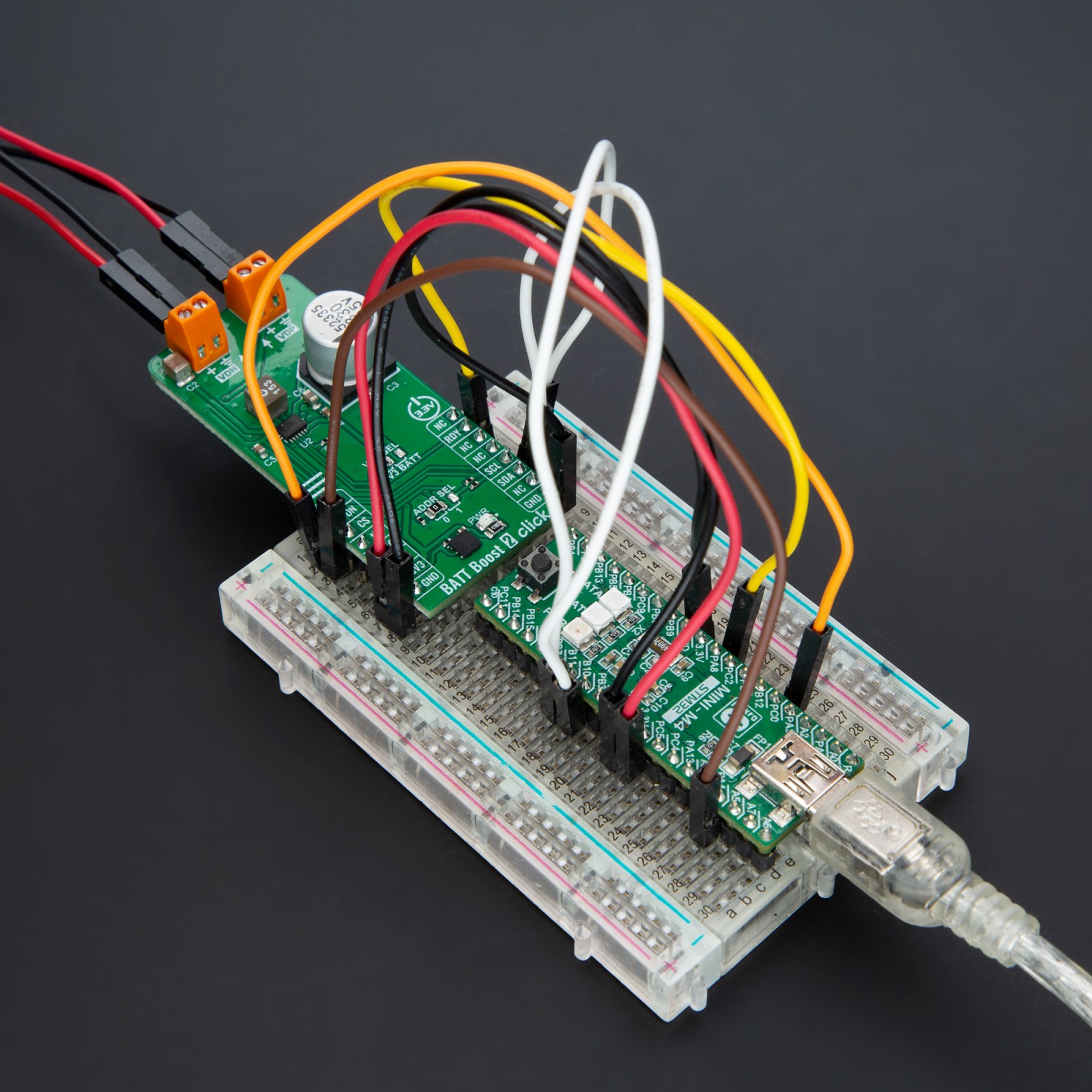
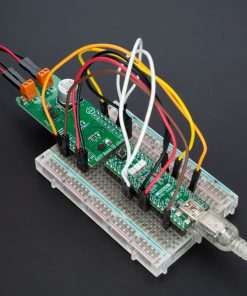
BATT Boost 2 Click uses a standard 2-wire I2C communication protocol, allowing the host MCU to control the NBM7100A, modify default configuration settings, and retrieve system information. The I2C interface supports clock frequencies up to 1MHz, with the device address selectable via the ADDR SEL jumper, which can be set to either position 0 or 1, corresponding to I2C addresses 0x2E or 0x2F. Additionally, several pins from the mikroBUS™ socket are used for further control of the NBM7100A: the ON pin manages the above-mentioned Auto mode, while the RDY pin provides a HIGH logic signal indicating that the NBM7100A is ready to deliver full power to the connected load.
This Click board™ can be operated only with a 3.3V logic voltage level. The board must perform appropriate logic voltage level conversion before using MCUs with different logic levels. Also, it comes equipped with a library containing functions and an example code that can be used as a reference for further development.
Specifications
Type
Boost
Applications
Ideal for powering wireless IoT sensors, industrial devices, and wearable consumer electronics that require efficient power management and frequent bursts of energy
On-board modules
NBM7100A – coin-cell battery-life booster with adaptive power optimization from Nexperia
Key Features
Battery life booster with adaptive power optimization, high-pulse load capability, VDP terminal with a maximum output current of 5mA for low-power components, Continuous, On-demand, and Auto modes for optimized power management, I2C interface with selectable address, status indicator, and more
Interface
I2C
Feature
ClickID
Compatibility
mikroBUS™
Click board size
L (57.15 x 25.4 mm)
Input Voltage
3.3V
Pinout diagram
This table shows how the pinout on BATT Boost 2 Click corresponds to the pinout on the mikroBUS™ socket (the latter shown in the two middle columns).
Onboard settings and indicators
| Label | Name | Default | Description |
|---|---|---|---|
| LD1 | PWR | – | Power LED Indicator |
| JP1 | ADDR SEL | Left | I2C Address Selection 0/1: Left position 0, Right position 1 |
| JP2 | VBAT SEL | Left | NBM7100A Supply Voltage Source Selection 3V3/BATT: Left position 3V3, Right position BATT |
BATT Boost 2 Click electrical specifications
| Description | Min | Typ | Max | Unit |
|---|---|---|---|---|
| Supply Voltage | – | 3.3 | – | V |
| VDH Terminal Output Current | – | – | 200 | mA |
| VDP Terminal Output Current | – | – | 5 | mA |
Software Support
We provide a library for the BATT Boost 2 Click as well as a demo application (example), developed using MIKROE compilers. The demo can run on all the main MIKROE development boards.
Package can be downloaded/installed directly from NECTO Studio Package Manager (recommended), downloaded from our LibStock™ or found on MIKROE github account.
Library Description
This library contains API for BATT Boost 2 Click driver.
Key functions
-
battboost2_set_vsetThis function is used to control the output voltage levels of the NBM7100ABQX, Coin cell battery life booster with adaptive power optimization on the BATT Boost 2 Click. -
battboost2_high_impedance_modeThis function is used to configures the VDH high-impedance mode in Standby and Active states of the NBM7100ABQX, Coin cell battery life booster with adaptive power optimization on the BATT Boost 2 Click board. -
battboost2_set_on_pin_stateThis function sets the desired states of the ON (RST) pin of the NBM7100ABQX, Coin cell battery life booster with adaptive power optimization on the BATT Boost 2 Click board.
Example Description
This library contains API for the BATT Boost 2 Click driver. This driver provides the functions to controle battery energy management device designed to maximize usable capacity from non-rechargeable.
void application_task ( void )
 {
     float vcap = 0;
     uint8_t status = 0;
     uint32_t chenergy = 0;

     if ( BATTBOOST2_STATUS_READY != battboost2_get_ready( &battboost2 ) )
     {
         if ( BATTBOOST2_OK == battboost2_set_op_mode( &battboost2, BATTBOOST2_OP_MODE_CHARGE ) )
         {
             log_printf( &logger, "nOperating state: Chargern" );
         }

         if ( BATTBOOST2_OK == battboost2_get_vcap( &battboost2, &vcap ) )
         {
             log_printf( &logger, " Capacitor Voltage: %.2f V rn", vcap );
         }

         if ( BATTBOOST2_OK == battboost2_get_chenergy( &battboost2, &chenergy ) )
         {
             log_printf( &logger, " Charge cycle count: %lu rn", chenergy );
         }
         Delay_ms( 1000 );
     }
     else
     {
         if ( BATTBOOST2_OK == battboost2_set_op_mode( &battboost2, BATTBOOST2_OP_MODE_ACTIVE ) )
         {
             log_printf( &logger, "nOperating state: Activern" );
             if ( BATTBOOST2_OK == battboost2_get_vcap( &battboost2, &vcap ) )
             {
                 log_printf( &logger, " Capacitor Voltage: %.2f V rn", vcap );
             }

             if ( BATTBOOST2_OK == battboost2_get_status( &battboost2, &status ) )
             {
                 if ( BATTBOOST2_STATUS_EW & status )
                 {
                     log_printf( &logger, " Status: Early warning.rn" );
                 }

                 if ( BATTBOOST2_STATUS_ALRM & status )
                 {
                     log_printf( &logger, " Status: Low output voltage in the Active state.rn" );
                 }
             }
         }
         Delay_ms( 1000 );
     }
 }
The full application code, and ready to use projects can be installed directly from NECTO Studio Package Manager (recommended), downloaded from our LibStock™ or found on MIKROE github account.
Other MIKROE Libraries used in the example:
- MikroSDK.Board
- MikroSDK.Log
- Click.BATTBoost2
Additional notes and informations
Depending on the development board you are using, you may need USB UART click, USB UART 2 Click or RS232 Click to connect to your PC, for development systems with no UART to USB interface available on the board. UART terminal is available in all MIKROE compilers.
mikroSDK
This Click board™ is supported with mikroSDK – MIKROE Software Development Kit. To ensure proper operation of mikroSDK compliant Click board™ demo applications, mikroSDK should be downloaded from the LibStock and installed for the compiler you are using.
For more information about mikroSDK, visit the official page.
Resources
Downloads
| Weight | 26 g |
|---|---|
| Brand | MikroElektronika |

