How does it work?
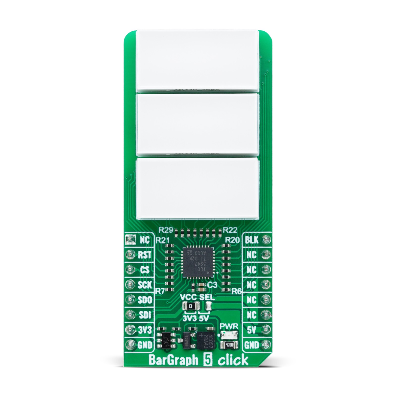
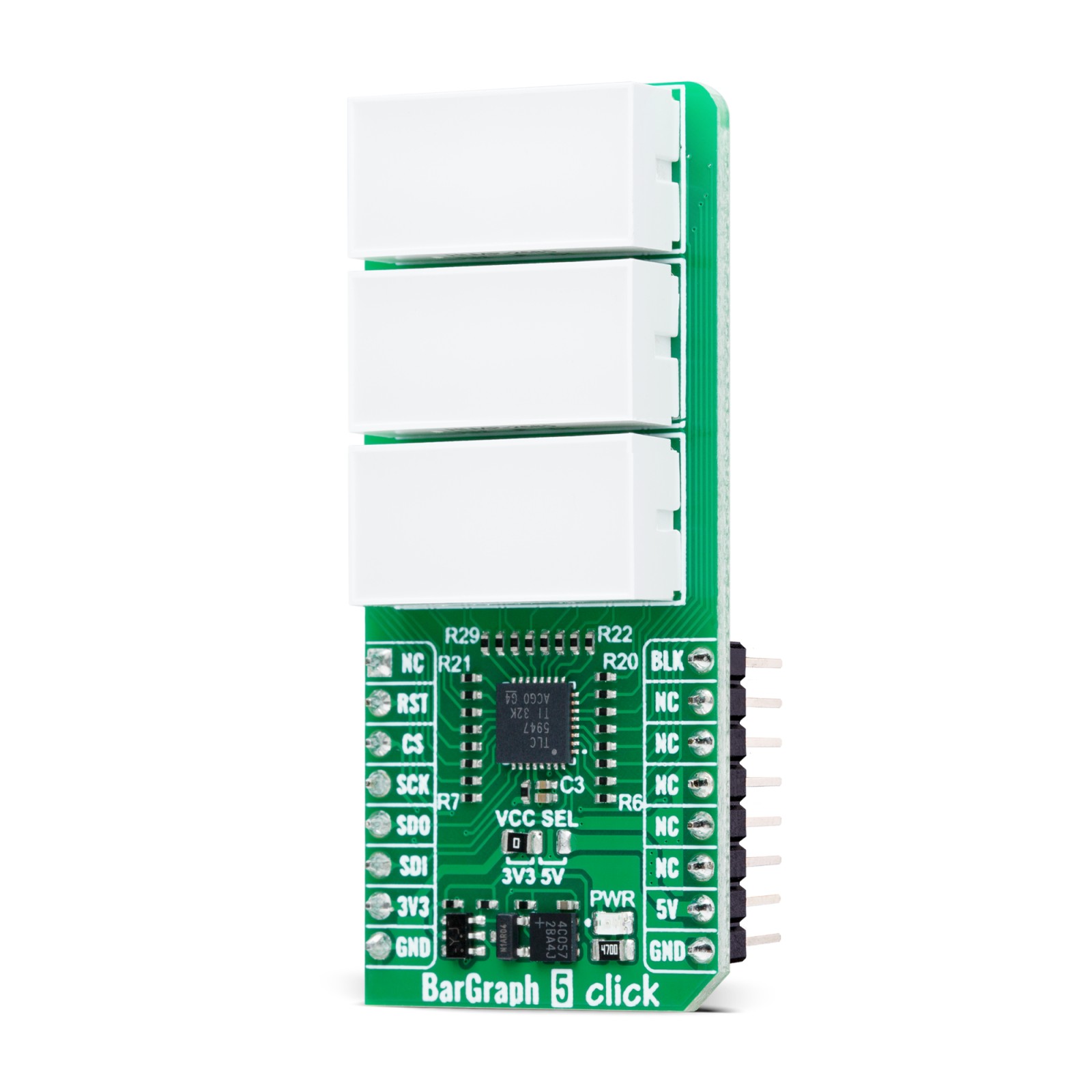
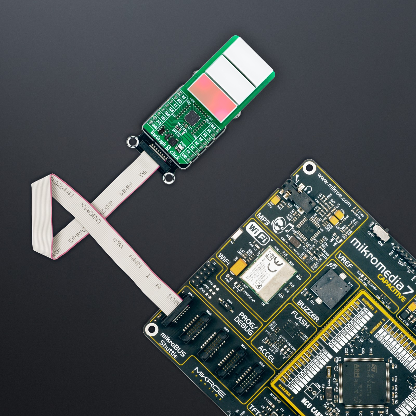
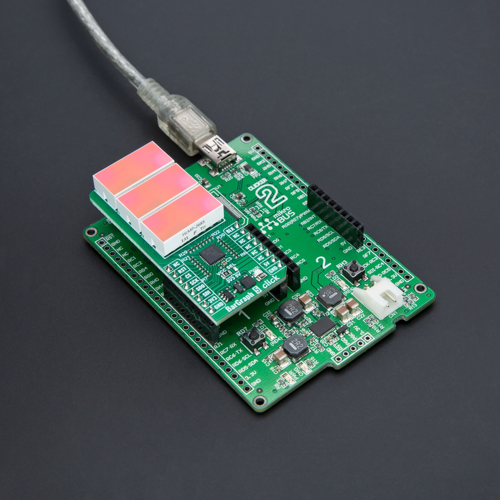
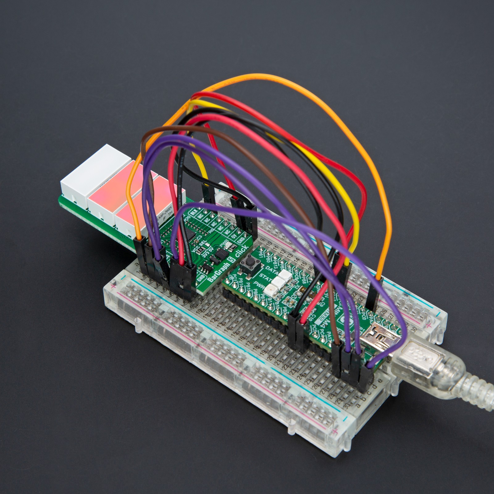
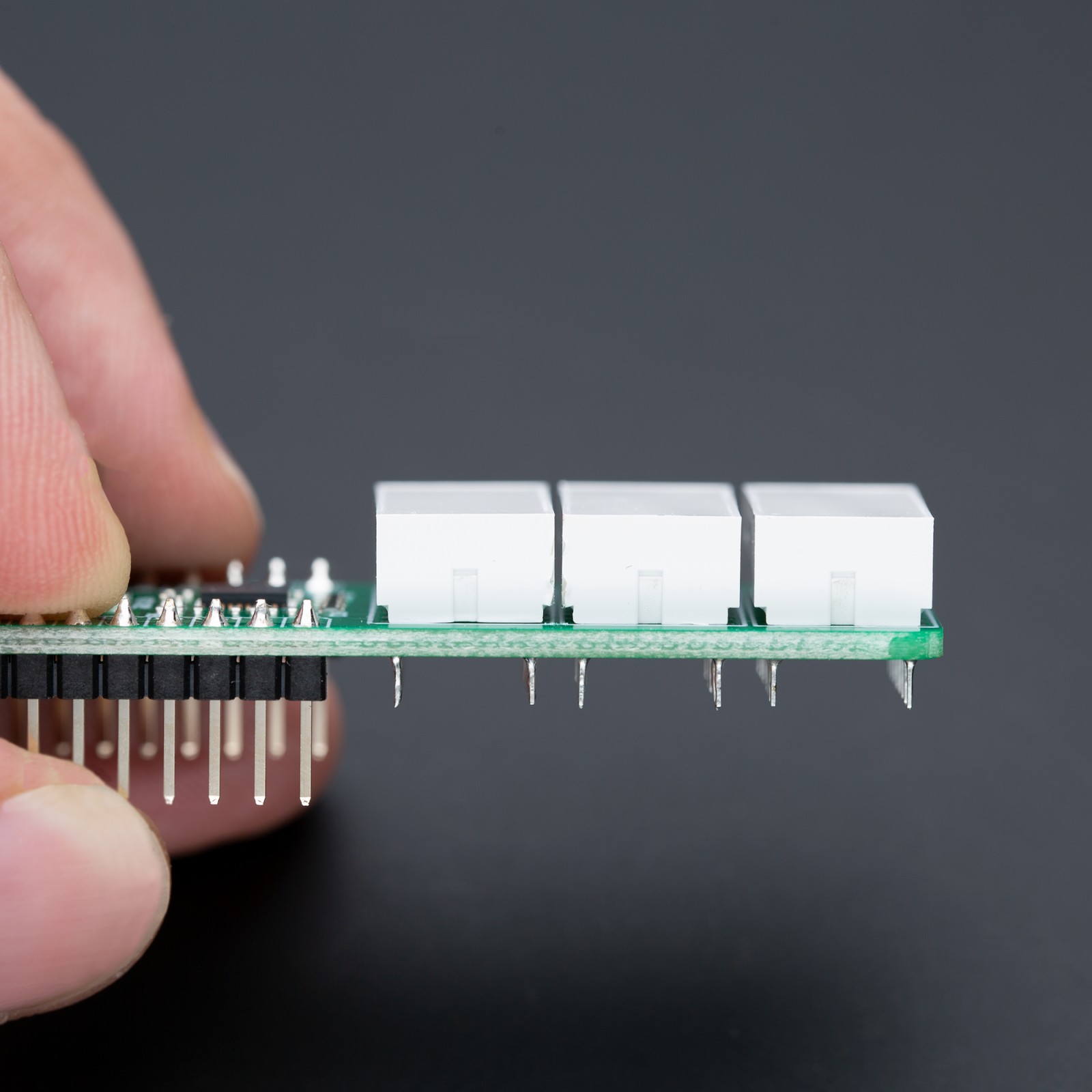
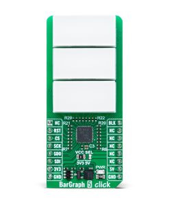
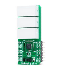
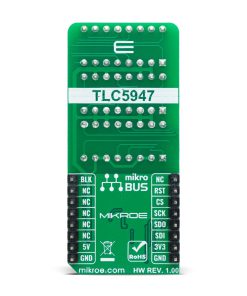
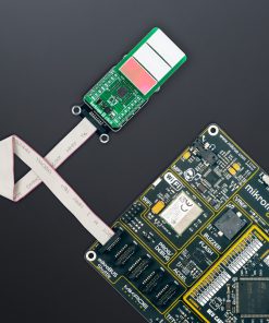
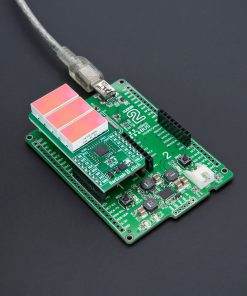
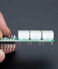
BarGraph 5 Click is based on three HLMP-2685 red LED bargraph displays from Broadcom Limited controlled by the TLC5947, a 12-bit PWM LED driver with an internal oscillator from Texas Instruments. These rectangular red light bars are housed in single-in-line packages, making them perfect for various industrial and commercial applications. Each lighting segment delivers a typical luminous intensity of 83.4mcd, with a peak wavelength of 626nm, ensuring high visibility. This Click board™ is ideal for applications requiring a large, bright, uniform light source, such as typical bargraph displays, front panel process status indicators, telecommunications equipment, machine message annunciators, and many other scenarios where clear and reliable visual feedback is needed.
The TLC5947 that controls these bars communicates with the host MCU through an SPI serial interface with a maximum clock frequency of up to 30MHz. In addition to the SPI communication signals, the board uses the BLK pin from the mikroBUS™ socket, functioning as a blanking control. When the BLK pin is set to a HIGH logic level, all bargraphs are turned OFF, and when it’s LOW, the bargraphs are activated. The board also includes a 2kΩ IREF resistor that sets the current for the TLC5947’s LED driver channels. This resistor ensures that the current for the bargraph LEDs is regulated at approximately 20mA, providing consistent brightness across the displays.
This Click board™ can operate with either 3.3V or 5V logic voltage levels selected via the VCC SEL jumper. This way, both 3.3V and 5V capable MCUs can use the communication lines properly. Also, this Click board™ comes equipped with a library containing easy-to-use functions and an example code that can be used as a reference for further development.
Specifications
Type
LED Segment
Applications
Ideal for bargraph displays, front panel status indicators, telecommunications equipment, machine message annunciators, and more
On-board modules
HLMP-2685 – red LED light bar from Broadcom Limited
Key Features
Three red LED bargraph displays, control via onboard LED driver, high visibility, large bright uniform light emitting areas, SPI interface, bar blanking control, and more
Interface
SPI
Feature
ClickID
Compatibility
mikroBUS™
Click board size
L (57.15 x 25.4 mm)
Input Voltage
3.3V or 5V
Pinout diagram
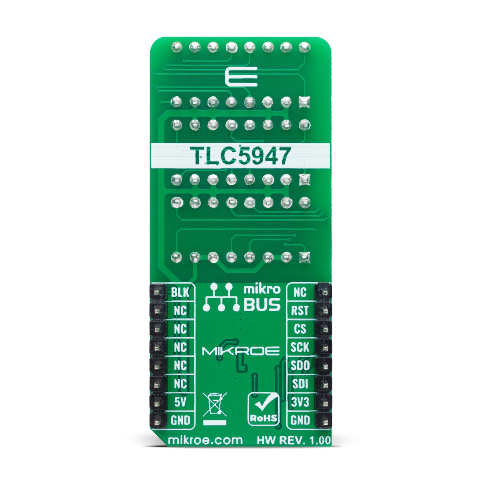
This table shows how the pinout on BarGraph 5 Click corresponds to the pinout on the mikroBUS™ socket (the latter shown in the two middle columns).
Onboard settings and indicators
Label | Name | Default | Description |
---|---|---|---|
LD1 | PWR | – | Power LED Indicator |
JP1 | VCC SEL | Left | Power Voltage Level Selection 3V3/5V: Left position 3V3, Right position 5V |
BarGraph 5 Click electrical specifications
Description | Min | Typ | Max | Unit |
---|---|---|---|---|
Supply Voltage | 3.3 | – | 5 | V |
Luminous Intensity Per Segment | – | 83.4 | – | mcd |
Peak Wavelength | – | 626 | – | nm |
Software Support
We provide a library for the BarGraph 5 Click as well as a demo application (example), developed using MIKROE compilers. The demo can run on all the main MIKROE development boards.
Package can be downloaded/installed directly from NECTO Studio Package Manager (recommended), downloaded from our LibStock™ or found on MIKROE github account.
Library Description
This library contains API for BarGraph 5 Click driver.
Key functions
-
bargraph5_set_bar_level
This function sets the level of a selected BarGraph channel at the selected brightness. -
bargraph5_output_enable
This function enables the BarGraph LEDs output by setting the BLANK pin to low logic state. -
bargraph5_output_disable
This function disables the BarGraph LEDs output by setting the BLANK pin to high logic state.
Example Description
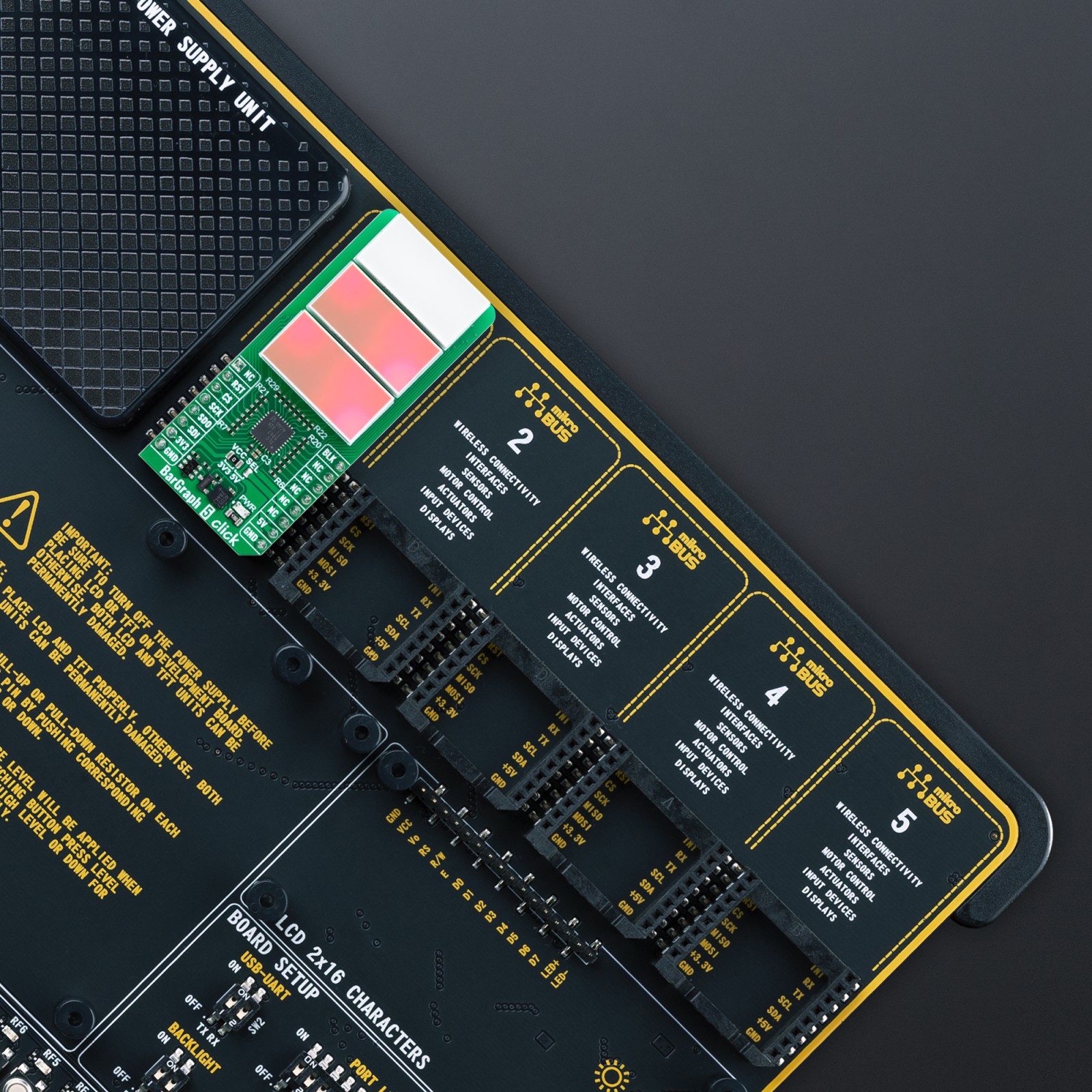
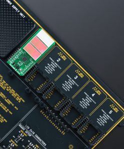
This example demonstrates the use of BarGraph 5 Click by changing the level of all BarGraph output channels.
void application_task ( void )
{
for ( bargraph5_level_t cnt = BARGRAPH5_LEVEL_0; cnt <= BARGRAPH5_LEVEL_4; cnt++ )
{
bargraph5_set_bar_level ( &bargraph5, BARGRAPH5_BAR_0, cnt, BARGRAPH5_BRIGHTNESS_DEFAULT );
bargraph5_set_bar_level ( &bargraph5, BARGRAPH5_BAR_1, BARGRAPH5_LEVEL_4 - cnt, BARGRAPH5_BRIGHTNESS_DEFAULT );
bargraph5_set_bar_level ( &bargraph5, BARGRAPH5_BAR_2, cnt, BARGRAPH5_BRIGHTNESS_DEFAULT );
bargraph5_set_bar_level ( &bargraph5, BARGRAPH5_BAR_3, BARGRAPH5_LEVEL_4 - cnt, BARGRAPH5_BRIGHTNESS_DEFAULT );
bargraph5_set_bar_level ( &bargraph5, BARGRAPH5_BAR_4, cnt, BARGRAPH5_BRIGHTNESS_DEFAULT );
bargraph5_set_bar_level ( &bargraph5, BARGRAPH5_BAR_5, BARGRAPH5_LEVEL_4 - cnt, BARGRAPH5_BRIGHTNESS_DEFAULT );
log_printf( &logger, " Bars 0-2-4 level: %urn", ( uint16_t ) cnt );
log_printf( &logger, " Bars 1-3-5 level: %urnn", ( uint16_t ) ( BARGRAPH5_LEVEL_4 - cnt ) );
Delay_ms ( 1000 );
}
}
The full application code, and ready to use projects can be installed directly from NECTO Studio Package Manager (recommended), downloaded from our LibStock™ or found on MIKROE github account.
Other MIKROE Libraries used in the example:
- MikroSDK.Board
- MikroSDK.Log
- Click.BarGraph5
Additional notes and informations
Depending on the development board you are using, you may need USB UART click, USB UART 2 Click or RS232 Click to connect to your PC, for development systems with no UART to USB interface available on the board. UART terminal is available in all MIKROE compilers.
mikroSDK
This Click board™ is supported with mikroSDK – MIKROE Software Development Kit. To ensure proper operation of mikroSDK compliant Click board™ demo applications, mikroSDK should be downloaded from the LibStock and installed for the compiler you are using.
For more information about mikroSDK, visit the official page.