How does it work?
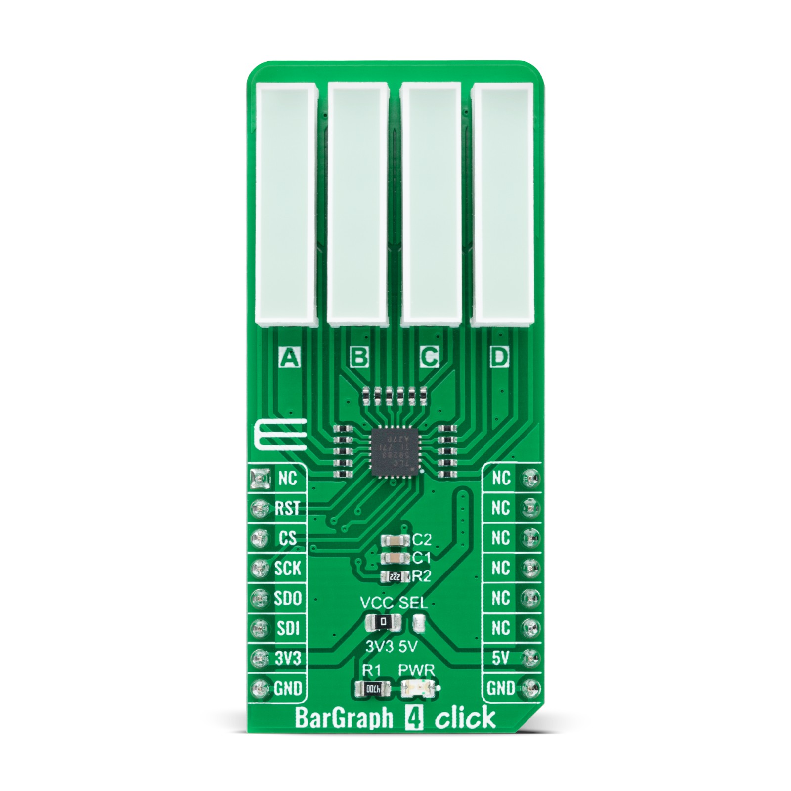
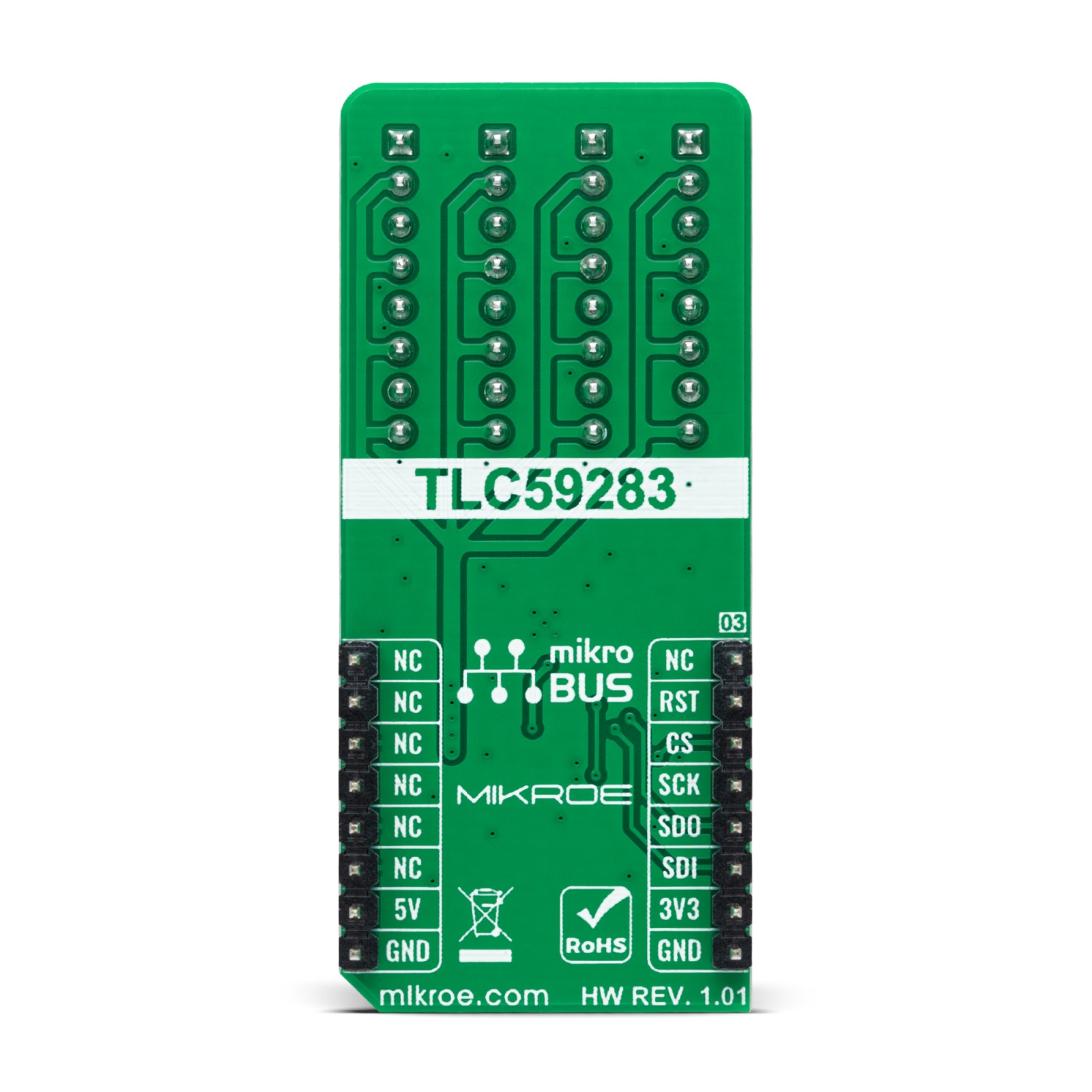
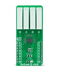
BarGraph 4 Click as its foundation uses the TLC59283, a 16-channel, constant-current sink light-emitting diode (LED) driver from Texas Instruments. Each channel can be individually controlled with a simple serial communications protocol compatible with 3.3V or 5V logic levels depending on the operating VCC. It also comes with a constant-current value of all 16 channels, determined by an external resistor R2 with a value of 2.2kΩ, limiting the current to 24mA. You can find the exact value of the current per channel, as well as the corresponding resistance value for a given current, in the attached datasheet.
In the upper part on the front side of the board, marked with the characters A, B, C, and D, four green four-segment LED bar graph displays, the HLMP-2550 are placed. The Green HLMP-2500 series LEDs use a liquid phase GaPepitaxial layer on a GaP substrate. These light bars are designed for various applications where a large bright light source is required, making this Click board™ suitable for creating different VU meters, status indicators, counters, and similar devices.
The TLC59283 communicates with MCU using the standard SPI serial interface with a maximum frequency of 35MHz. It has a 16-bit shift register and an output ON/OFF data latch. Both shift register and data latch are 16 bits long and used to turn the constant-current outputs on and off. It also comes with one GPIO pin, routed on the RST pin of the mikroBUS™ socket, used to turn off all outputs during Power-On and output data latching to prevent unwanted image displays during these times.
When the device is initially powered on, the data in the 16-bit shift register and output on or off data latch are not set to default values. Therefore, the output ON/PFF data must be written to the data latch before turning the constant-current output ON. The RST pin should be high when powered on because the constant-current may be turned ON due to random data in the output on or off data latch.
This Click board™ can operate with both 3.3V and 5V logic voltage levels selected via the VCC SEL jumper. This way, it is allowed for both 3.3V and 5V capable MCUs to use the SPI communication lines properly. However, the Click board™ comes equipped with a library containing easy-to-use functions and an example code that can be used, as a reference, for further development.
Specifications
Type
Bargraph,LED Segment
Applications
Can be used for creating various types of VU meters, status indicators, different types of counters, and similar devices
On-board modules
TLC59283 – 16-channel, constant-current sink light-emitting diode (LED) driver from Texas Instruments
Key Features
16-channel constant-current LED Driver, each channel individually controlled, output force-off pin, four green four-segment LED bar graph displays, bright uniform light emitting areas, and more
Interface
SPI
Feature
No ClickID
Compatibility
mikroBUS™
Click board size
L (57.15 x 25.4 mm)
Input Voltage
3.3V or 5V
Pinout diagram
This table shows how the pinout on BarGraph 4 Click corresponds to the pinout on the mikroBUS™ socket (the latter shown in the two middle columns).
Onboard settings and indicators
Label | Name | Default | Description |
---|---|---|---|
LD1 | PWR | – | Power LED Indicator |
JP1 | VCC SEL | Left | Logic Level Voltage Selection 3V3/5V: Left position 3V3, Right position 5V |
BarGraph 4 Click electrical specifications
Description | Min | Typ | Max | Unit |
---|---|---|---|---|
Supply Voltage | 3.3 | – | 5 | V |
Output Current per Channel | – | 24 | – | mA |
Operating Temperature Range | -40 | +25 | +85 | °C |
Software Support
We provide a library for the BarGraph 4 Click as well as a demo application (example), developed using MikroElektronika compilers. The demo can run on all the main MikroElektronika development boards.
Package can be downloaded/installed directly from NECTO Studio Package Manager(recommended way), downloaded from our LibStock™ or found on Mikroe github account.
Library Description
This library contains API for BarGraph 4 Click driver.
Key functions:
bargraph4_cfg_setup
– Config Object Initialization function.bargraph4_init
– Initialization function.
Examples description
This example demonstrates the use of BarGraph 4 click board.
The application is composed of three sections :
void application_task ( void ) { for ( bargraph4_level_t cnt = BARGRAPH4_LEVEL_0; cnt <= BARGRAPH4_LEVEL_4; cnt++ ) { bargraph4_set_channel_level( &bargraph4, BARGRAPH4_CHANNEL_A, cnt ); bargraph4_set_channel_level( &bargraph4, BARGRAPH4_CHANNEL_B, cnt ); bargraph4_set_channel_level( &bargraph4, BARGRAPH4_CHANNEL_C, cnt ); bargraph4_set_channel_level( &bargraph4, BARGRAPH4_CHANNEL_D, cnt ); log_printf( &logger, " All channels set to level %urnn", ( uint16_t ) cnt ); Delay_ms( 1000 ); } }
The full application code, and ready to use projects can be installed directly from NECTO Studio Package Manager(recommended way), downloaded from our LibStock™ or found on Mikroe github account.
Other mikroE Libraries used in the example:
- MikroSDK.Board
- MikroSDK.Log
- Click.BarGraph4
Additional notes and informations
Depending on the development board you are using, you may need USB UART click, USB UART 2 click or RS232 click to connect to your PC, for development systems with no UART to USB interface available on the board. The terminal available in all MikroElektronika compilers, or any other terminal application of your choice, can be used to read the message.
mikroSDK
This Click board™ is supported with mikroSDK – MikroElektronika Software Development Kit. To ensure proper operation of mikroSDK compliant Click board™ demo applications, mikroSDK should be downloaded from the LibStock and installed for the compiler you are using.
For more information about mikroSDK, visit the official page.