Balancer 5 Click
R320.00 ex. VAT
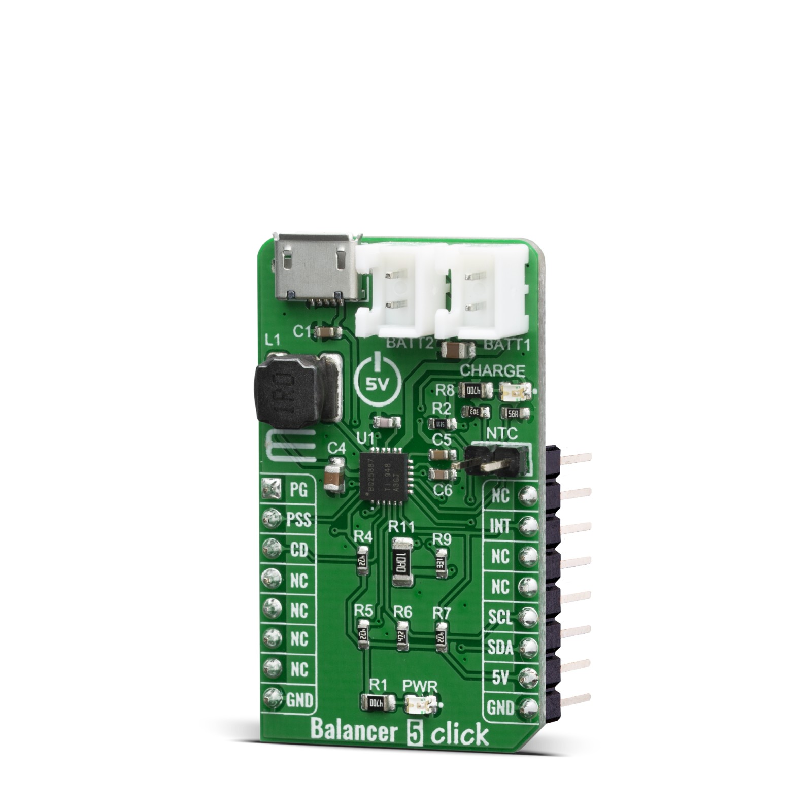
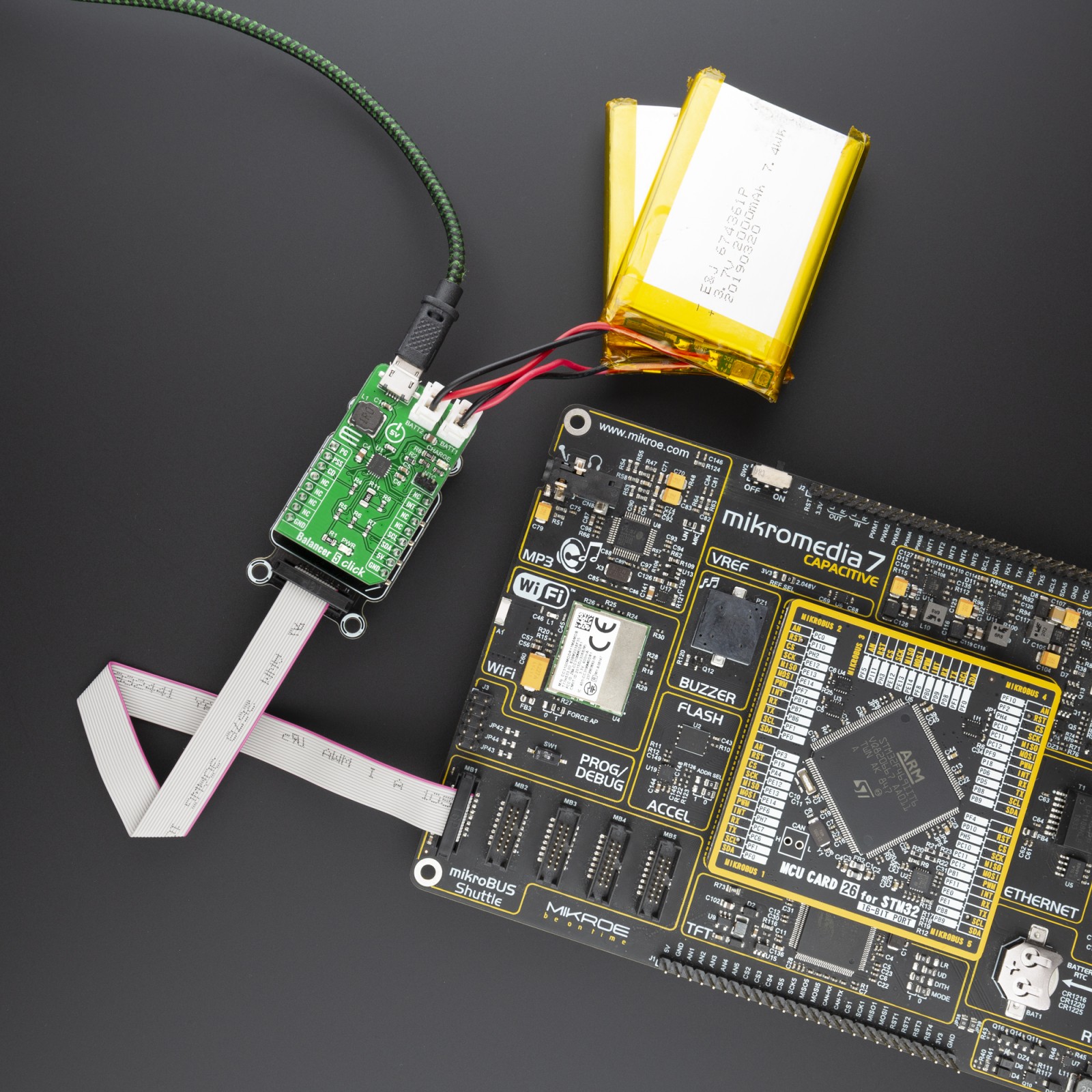
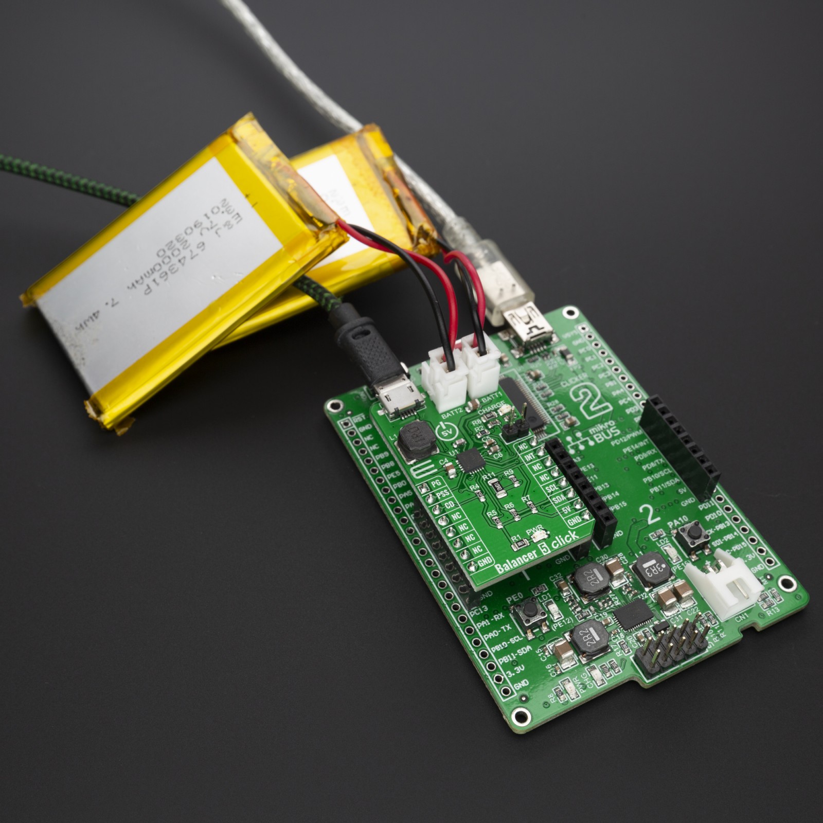
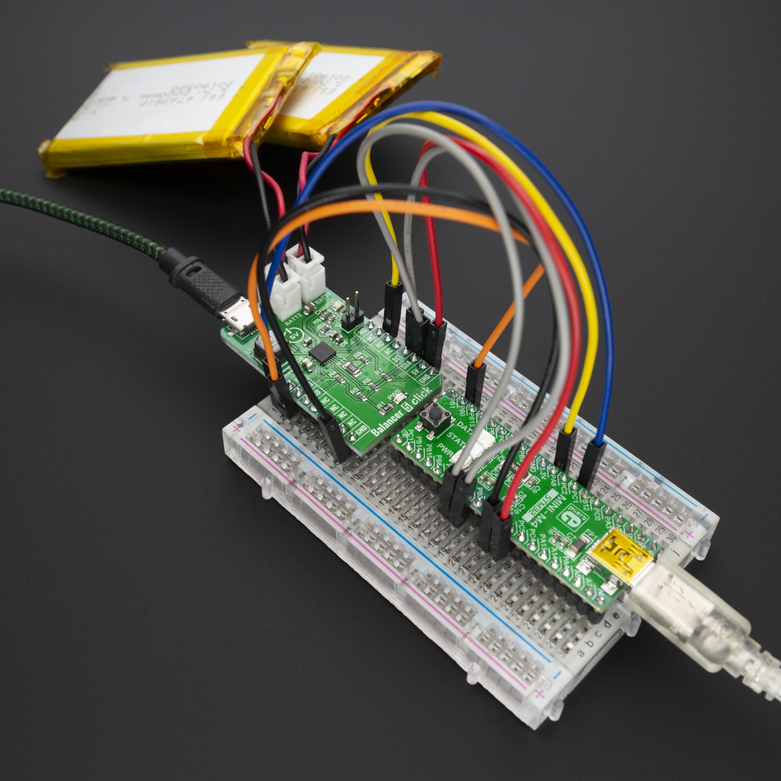
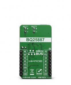
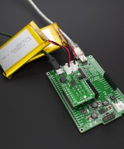
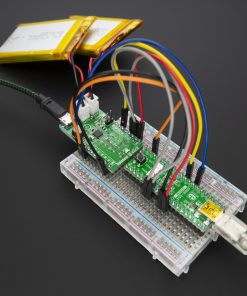
Balancer 5 Click is an intelligent 2-cell Li-Ion battery charger, system power manager, and a battery fuel gauge Click board™. Balancer 5 click is based on BQ25887 controller which has some extra features enabling charging without too much hassle. As a system power distributor, it can supply up to 3.3A to a connected battery. By utilizing an externally connected USB power supply, it can charge a 2-cell Li-Ion battery. A dedicated power management IC with the optimized smart power control allows very efficient management of the available power.
The Balancer 5 click is supported by a mikroSDK compliant library, which includes functions that simplify software development. This Click board™ comes as a fully tested product, ready to be used on a system equipped with the mikroBUS™ socket.
Stock: Lead-time applicable.
| 5+ | R304.00 |
| 10+ | R288.00 |
| 15+ | R272.00 |
| 20+ | R261.76 |
How does it work?
Balancer 5 click is based on the BQ25887 form Texas Instruments– fully integrated 2-cell Li-ion battery charger IC ideal for portable applications with cell balancing. The BQ25887 optimizes the charging two battery with balancing. The input voltage range from USB connector can be as high as 5.5V, battery can be charge with up to 3.3A. When the input voltage exceeds the OVP (Over Voltage Protection) threshold, it will turn off the charging MOSFET to avoid overheating of the chip. Along with its small physical size, the low number of external components makes this IC ideally suitable for various applications.
.jpg)
As a Lithium Ion batteries require a very accurate current and voltage for charging, Balancer 5 click can be a perfect solution for such a task. Balancer 5 click is equipped with a highly integrated Li-Ion battery charger, supporting intelligent, constant-current, constant voltage (CCCV), temperature-regulated battery charger charges a 2-cell lithium-ion (Li+) cell batteries. This click has a charging current control IC over I2C interface which ensures perfect and efficient charging. Balancer 5 click can be used as a part of the power supply and distribution system in many applications: different kinds of handheld appliances, portable media players, portable audio players, and other general-purpose battery-operated electronic devices.
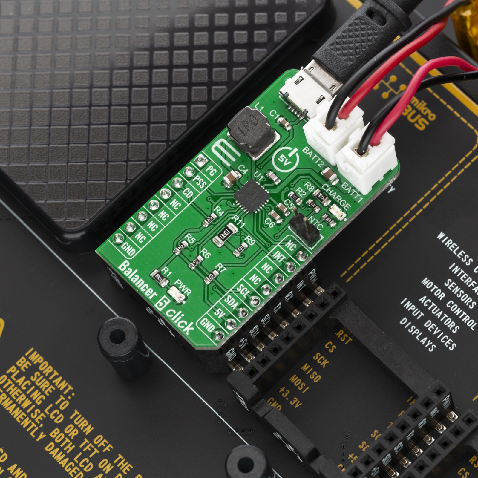
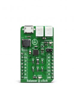
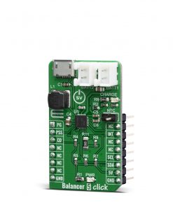
On the left side of the click board is an input USB connector, where the external voltage as high as 5.5V can be applied. Two connectors on the right side is reserved for a Li-Ion batteries with corresponding markings, right connector is for first batteries and left connectr is for secound batteries. When connected to power source, the green CHARGE LED will indicate it, LOW indicates charge in progress. HIGH indicates charge complete or charge disabled. When any fault occurs, the STAT pin blinks at 1Hz. The STAT function can be disabled when the STAT_DIS bit is set.
On right side is 1×2 male header for connect a NTC (Negative temperature Coefficient) resistor. Connect a negative temperature coefficient thermistor. Program temperature window with a resistor divider from REGN to TS to GND. Charge suspends when TS pin is out of range. Recommend 103AT-2 thermistor.
The voltage range which can be used to power up the Balancer 5 click, allows for it to work with 5V capable MCUs.
Specifications
Type
Battery charger
Applications
Balancer 5 is a perfect choice for development 2S lithium-ion (Li+) cell battery charging with cell balancing.
On-board modules
BQ25887, a highly Integrated linear battey charger from Texas Instruments.
Key Features
Optimized for USB input and 2-cell Li-Ion, Input current limit to support USB2.0, USB3.0, Battery temperature sensing in charge.
Interface
GPIO,I2C
Feature
No ClickID
Compatibility
mikroBUS™
Click board size
M (42.9 x 25.4 mm)
Input Voltage
5V
Pinout diagram
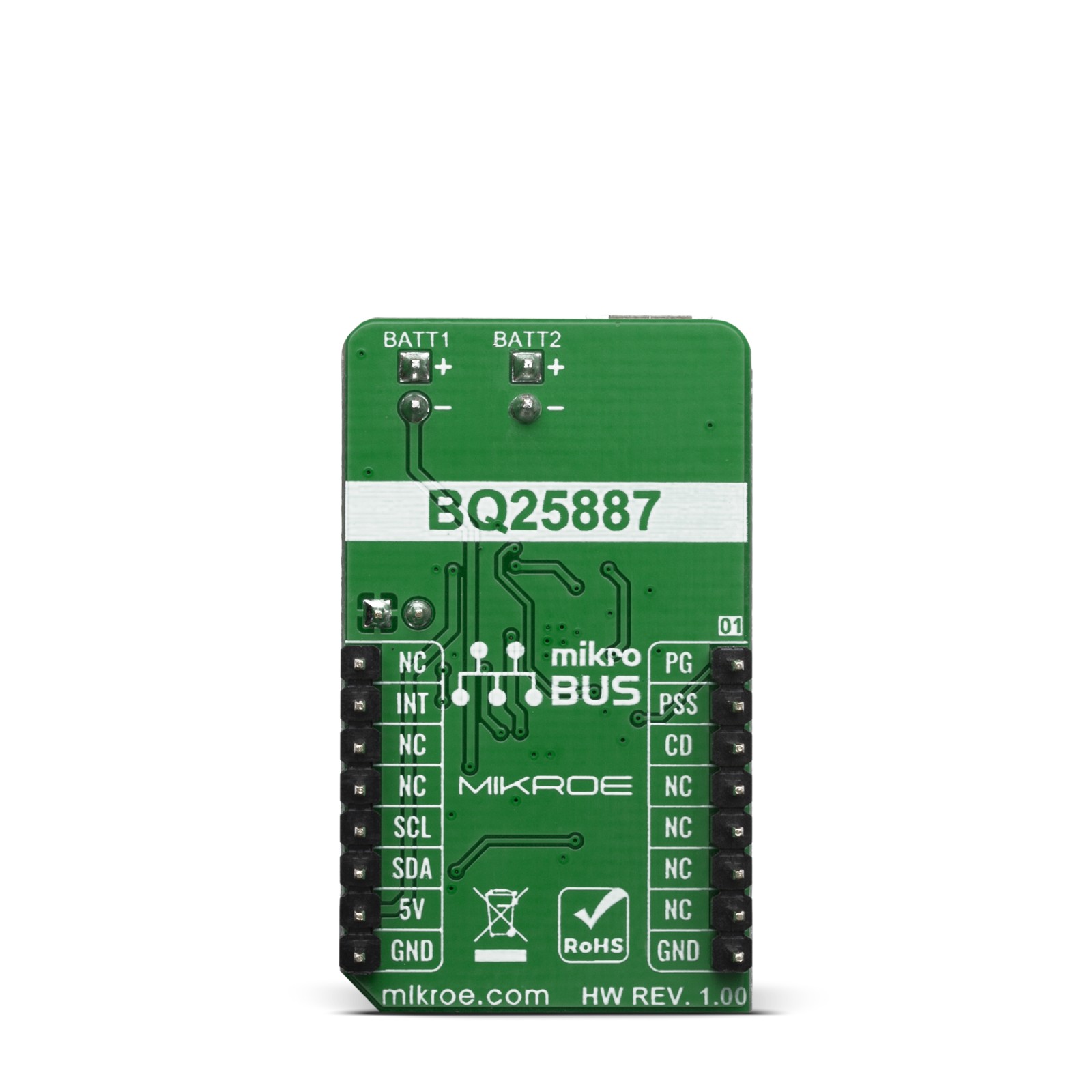
This table shows how the pinout on Balancer 5 click corresponds to the pinout on the mikroBUS™ socket (the latter shown in the two middle columns).
Onboard settings and indicators
| Label | Name | Default | Description |
|---|---|---|---|
| LD1 | PWR | – | Power LED indicator |
| LD2 | STAT | – | Charge status indicator |
| BAT1 | BATT1 | – | Battery connector |
| BAT2 | BATTT2 | – | Battery connector |
| CN1 | USB | – | USB input coltage connector |
| Rt1 | NTC | – | Option battery thermistor connector ( Should be not connect if not used) |
Balancer 5 Click electrical specifications
| Description | Min | Typ | Max | Unit |
|---|---|---|---|---|
| Input Voltage (at USB CN1 connector) | 3.9 | 5 | 5.5 | V |
| System output voltage (at BATT1 and BATT2 connector) | – | – | 9.2 | V |
| Charging Current (max current selectable by IOUT SEL) | – | 0.5 | 2.2 | A |
Software Support
We provide a library for the Balancer 5 Click on our LibStock page, as well as a demo application (example), developed using MikroElektronika compilers. The demo can run on all the main MikroElektronika development boards.
Library Description
Library provides functions for controling pin state and reading it from device, and reading and writing data to device.
Key functions:
void balancer5_charge ( uint8_t state )– Control device charging sateuint8_t balancer5_read_data ( uint8_t reg_addr )– Reads and returns one Byte of data from registarvoid balancer5_write_data ( uint8_t reg_addr, uint8_t write_data )– Writes one Byte of data to registar
Examples description
The application is composed of three sections :
- System Initialization – Initialization of I2C module and setting pins to output
- Application Initialization – Checks ID, starts charging, reads charge status registers and configures ADC
- Application Task – Reads ADC values from registers and logs it
void application_task ( )
{
    temp_data = balancer5_read_data( BALANCER5_REG_IBUS_ADC1 );
    temp_uint_data = temp_data;
    temp_uint_data <<= 8;
    temp_data = balancer5_read_data( BALANCER5_REG_IBUS_ADC0 );
    temp_uint_data |= temp_data;
    IntToStr( temp_uint_data, demo_txt );
    mikrobus_logWrite( "- IBUS:", _LOG_TEXT );
    mikrobus_logWrite( demo_txt, _LOG_TEXT );
    mikrobus_logWrite( " mA", _LOG_LINE );

    temp_data = balancer5_read_data( BALANCER5_REG_ICHG_ADC1 );
    temp_uint_data = temp_data;
    temp_uint_data <<= 8;
    temp_data = balancer5_read_data( BALANCER5_REG_ICHG_ADC0 );
    temp_uint_data |= temp_data;
    WordToStr( temp_uint_data, demo_txt );
    mikrobus_logWrite( "- ICHG:", _LOG_TEXT );
    mikrobus_logWrite( demo_txt, _LOG_TEXT );
    mikrobus_logWrite( " mA", _LOG_LINE );

    temp_data = balancer5_read_data( BALANCER5_REG_VBAT_ADC1 );
    temp_uint_data = temp_data;
    temp_uint_data <<= 8;
    temp_data = balancer5_read_data( BALANCER5_REG_VBAT_ADC0 );
    temp_uint_data |= temp_data;
    IntToStr( temp_uint_data, demo_txt );
    mikrobus_logWrite( "- VBAT:", _LOG_TEXT );
    mikrobus_logWrite( demo_txt, _LOG_TEXT );
    mikrobus_logWrite( " mV", _LOG_LINE );

    temp_data = balancer5_read_data( BALANCER5_REG_VBUS_ADC1 );
    temp_uint_data = temp_data;
    temp_uint_data <<= 8;
    temp_data = balancer5_read_data( BALANCER5_REG_VBUS_ADC0 );
    temp_uint_data |= temp_data;
    IntToStr( temp_uint_data, demo_txt );
    mikrobus_logWrite( "- VBUS:", _LOG_TEXT );
    mikrobus_logWrite( demo_txt, _LOG_TEXT );
    mikrobus_logWrite( " mV", _LOG_LINE );

    temp_data = balancer5_read_data( BALANCER5_REG_VCELLTOP_ADC1 );
    temp_uint_data = temp_data;
    temp_uint_data <<= 8;
    temp_data = balancer5_read_data( BALANCER5_REG_VCELLTOP_ADC0 );
    temp_uint_data |= temp_data;
    IntToStr( temp_uint_data, demo_txt );
    mikrobus_logWrite( "- VCELLTOP:", _LOG_TEXT );
    mikrobus_logWrite( demo_txt, _LOG_TEXT );
    mikrobus_logWrite( " mV", _LOG_LINE );

    temp_data = balancer5_read_data( BALANCER5_REG_VCELLBOT_ADC1 );
    temp_uint_data = temp_data;
    temp_uint_data <<= 8;
    temp_data = balancer5_read_data( BALANCER5_REG_VCELLBOT_ADC0 );
    temp_uint_data |= temp_data;
    IntToStr( temp_uint_data, demo_txt );
    mikrobus_logWrite( "- VCELLBOT:", _LOG_TEXT );
    mikrobus_logWrite( demo_txt, _LOG_TEXT );
    mikrobus_logWrite( " mV", _LOG_LINE );

    temp_data = balancer5_read_data( BALANCER5_REG_TS_ADC1 );
    temp_uint_data = temp_data;
    temp_uint_data <<= 8;
    temp_data = balancer5_read_data( BALANCER5_REG_TS_ADC0 );
    temp_uint_data |= temp_data;
    temp_float_data = temp_uint_data;
    temp_float_data *= 0.098;
    FloatToStr( temp_float_data, demo_txt );
    mikrobus_logWrite( "- TS:", _LOG_TEXT );
    mikrobus_logWrite( demo_txt, _LOG_TEXT );
    mikrobus_logWrite( " %", _LOG_LINE );

    temp_data = balancer5_read_data( BALANCER5_REG_TDIE_ADC1 );
    temp_uint_data = temp_data;
    temp_uint_data <<= 8;
    temp_data = balancer5_read_data( BALANCER5_REG_TDIE_ADC0 );
    temp_uint_data |= temp_data;
    temp_float_data = temp_uint_data;
    temp_float_data *= 0.5;
    FloatToStr( temp_float_data, demo_txt );
    mikrobus_logWrite( "- TDIE:", _LOG_TEXT );
    mikrobus_logWrite( demo_txt, _LOG_TEXT );
    mikrobus_logWrite( log_degree, _LOG_LINE );

    mikrobus_logWrite( "____________________", _LOG_LINE );
    Delay_ms( 5000 );
}
Additional Functions :
- void charger_status_1_handler ( uint8_t cs1_data ) – Handles data from charger status 1 and logs it
- void charger_status_2_handler ( uint8_t cs2_data ) – Handles data from charger status 2 and logs it
The full application code, and ready to use projects can be found on our LibStock page.
Other mikroE Libraries used in the example:
- Conversions
- UART
- I2C
Additional notes and informations
Depending on the development board you are using, you may need USB UART click, USB UART 2 click or RS232 click to connect to your PC, for development systems with no UART to USB interface available on the board. The terminal available in all MikroElektronika compilers, or any other terminal application of your choice, can be used to read the message.
mikroSDK
This Click board™ is supported with mikroSDK – MikroElektronika Software Development Kit. To ensure proper operation of mikroSDK compliant Click board™ demo applications, mikroSDK should be downloaded from the LibStock and installed for the compiler you are using.
For more information about mikroSDK, visit the official page.
Resources
Downloads
| Weight | 20 g |
|---|---|
| Brand | MikroElektronika |


