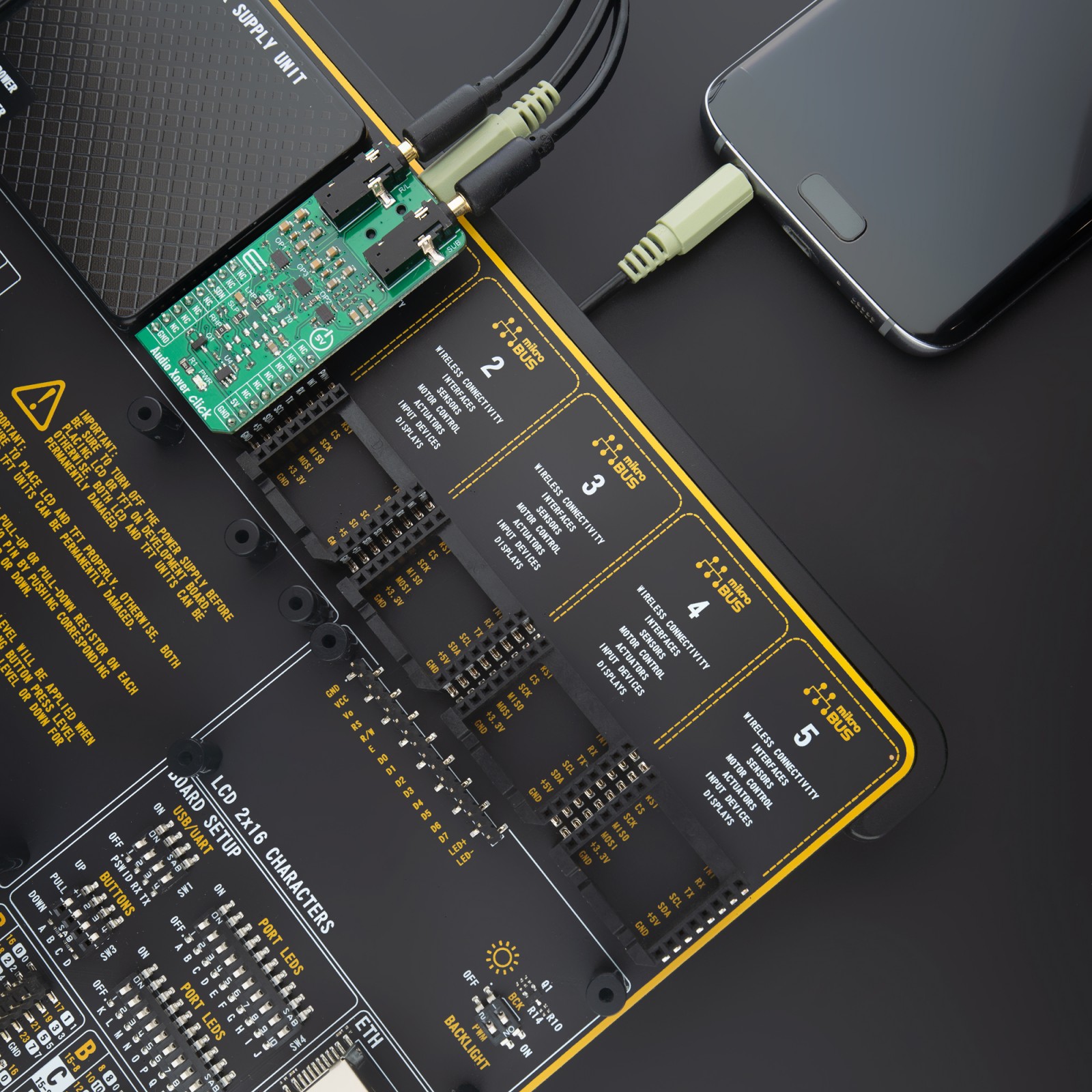
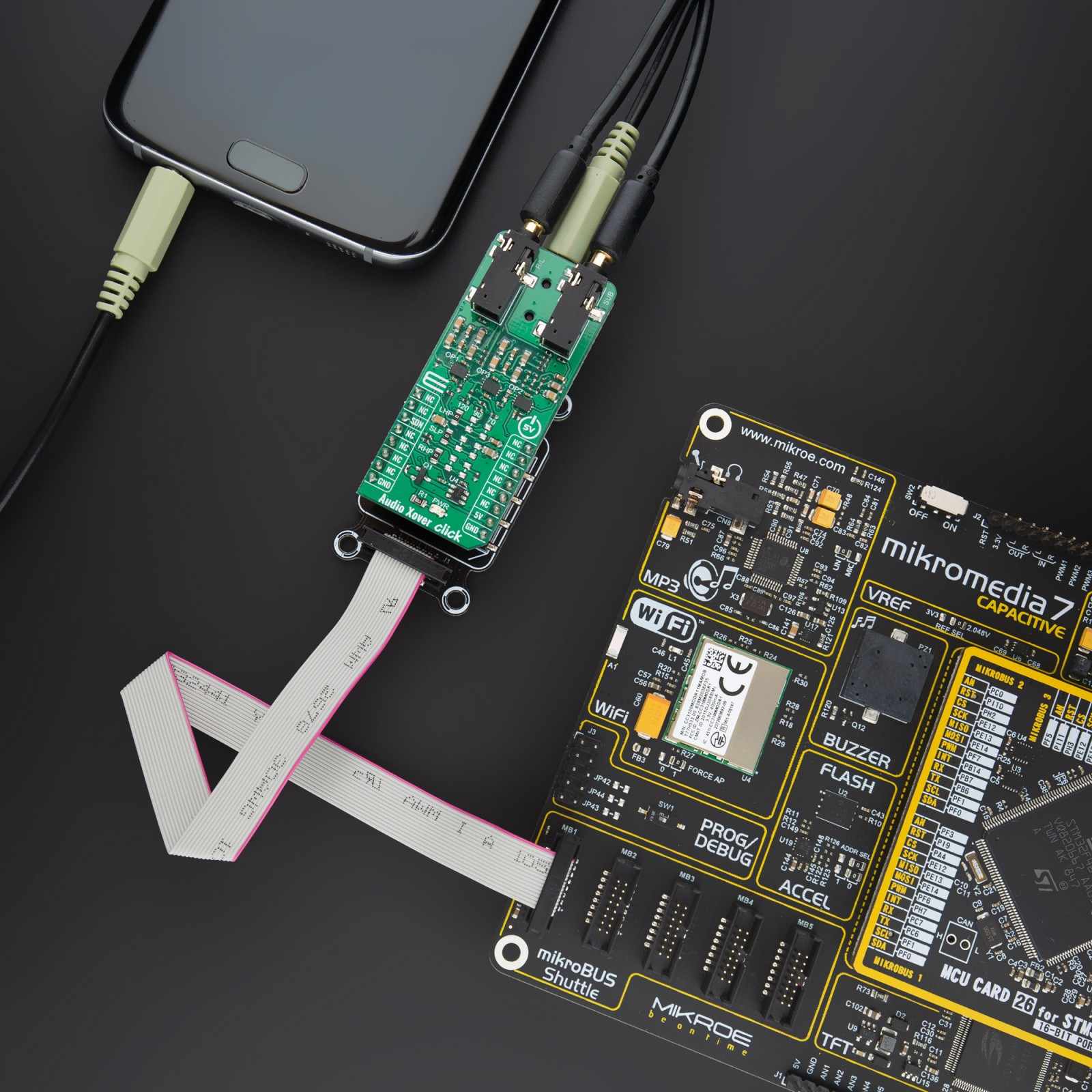
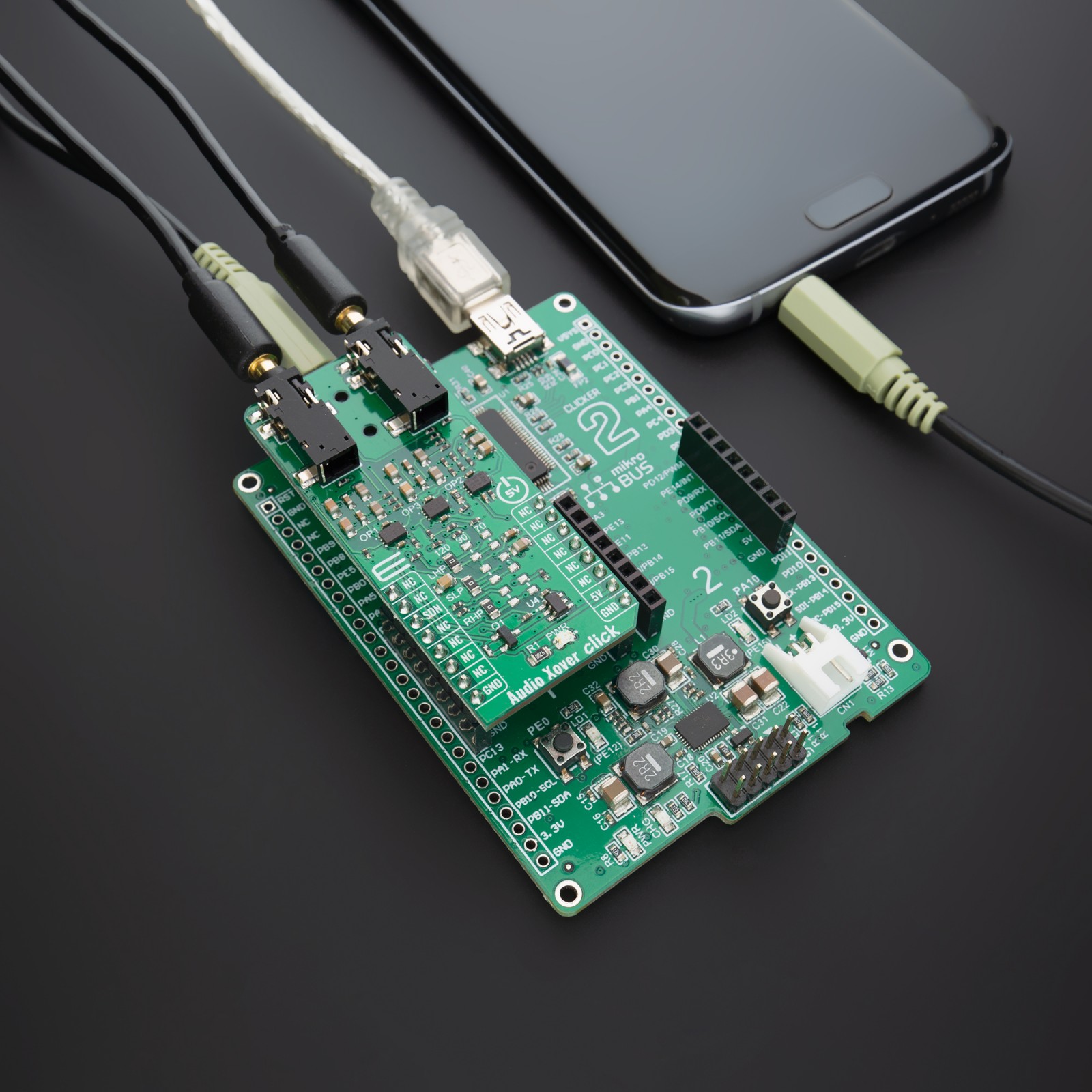
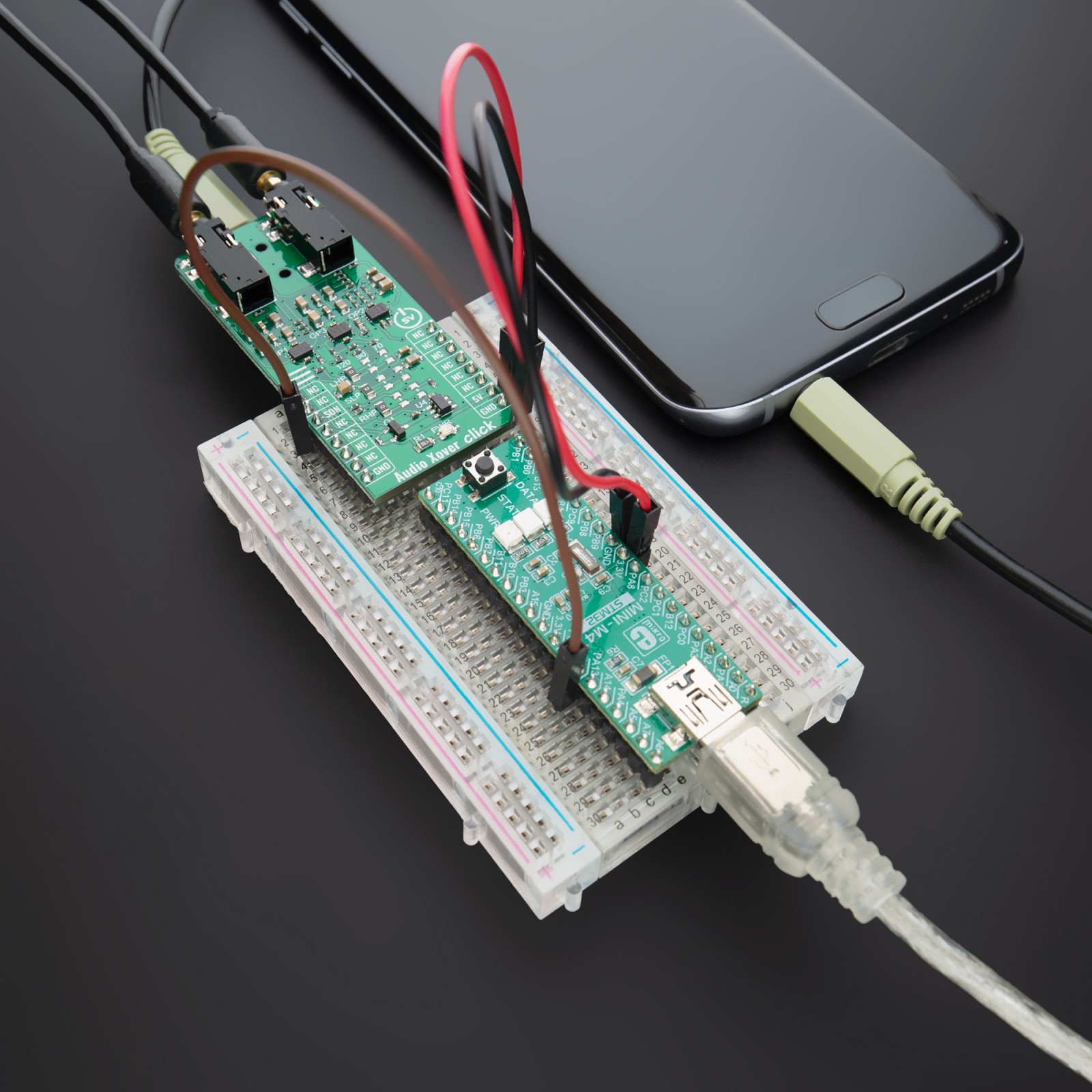
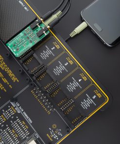
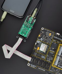
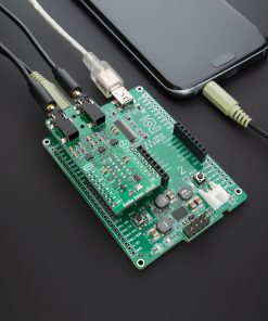
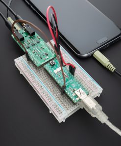
How does it work
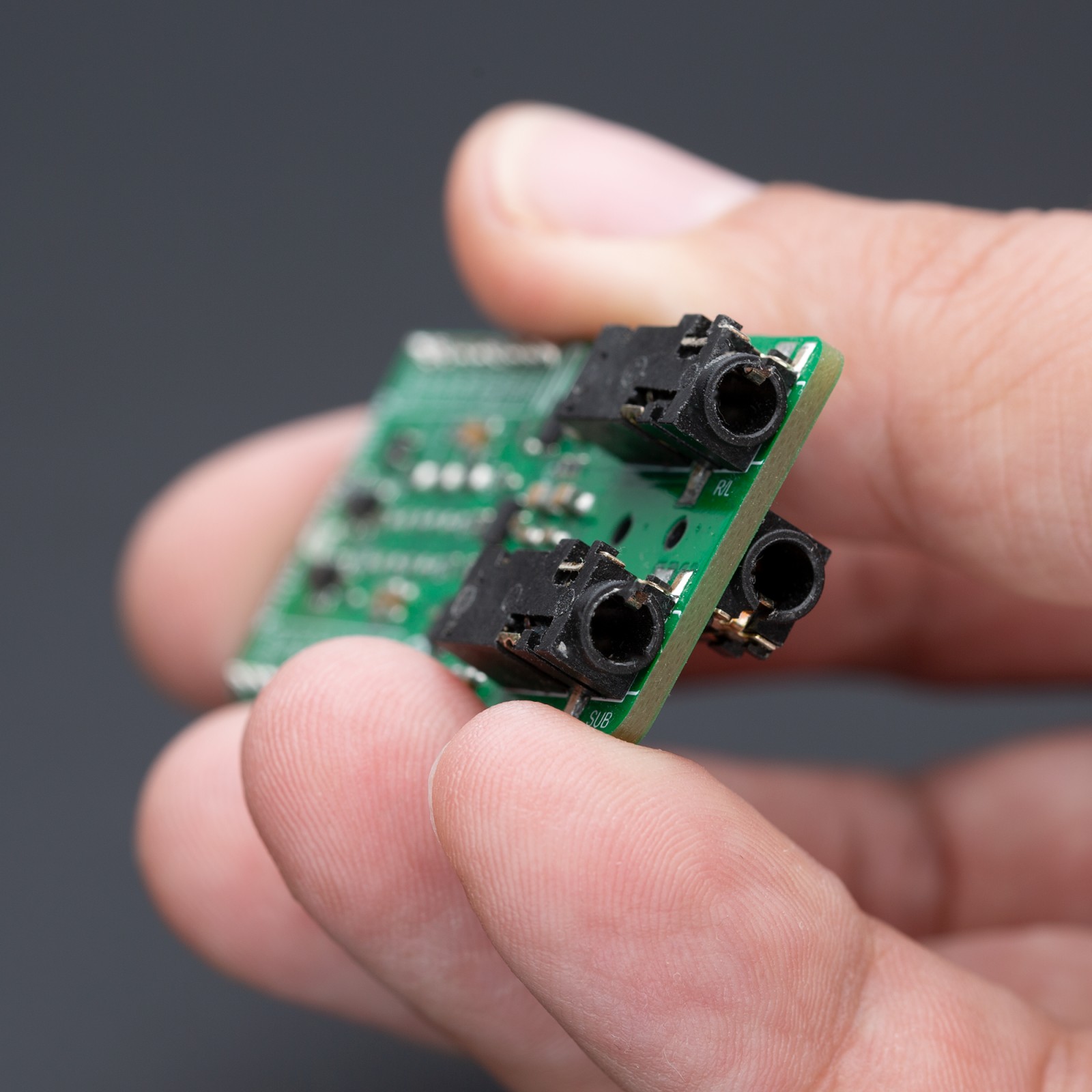
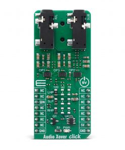
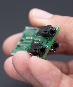
Audio Xover Click enhances audio systems by efficiently managing frequency distribution across speakers. It uses three precise Butterworth filters, based on Microchip’s MCP6H012 operational amplifiers, each dedicated to a specific speaker, with adjustable cutoff frequencies of 120Hz, 90Hz, and 70Hz. Butterworth filters are highly regarded for their maximally flat frequency response within the passband, ensuring the sharpest possible roll-off without any peaking. This performance is achieved using a second-order, two-pole design with a damping ratio of 0.707. Audio Xover Click enhances sound quality in home audio systems, ensures high-fidelity reproduction in professional PA systems and recording studios, and optimizes car speaker performance for a balanced audio experience.
As is well known, audio crossovers play a crucial role in audio systems, splitting an audio signal into multiple frequency ranges. This separation allows each frequency range to be directed to drivers (speakers) designed for those specific frequencies, such as woofers for low frequencies, mid-range drivers for middle frequencies, and tweeters for high frequencies. Unlike passive crossovers, which divide an amplified signal among various drivers, active crossovers like those implemented in the Audio Xover Click split the audio signal before amplification. This method directs the signal to multiple power amplifiers, each linked to a specific driver type.
One significant advantage of active crossovers is their independence from amplifier power levels. Since active crossovers handle the signal before it enters the amplifier, they are unaffected by the amplifiers’ power. Additionally, active crossovers are less sensitive to temperature variations, ensuring consistent performance and accuracy. Another benefit is channel isolation; if one amplifier channel clips in an active crossover system, the distortion only affects that particular channel, leaving the other channels unaffected.
This Click board™ can be operated only with a 5V logic voltage level. The board must perform appropriate logic voltage level conversion before using MCUs with different logic levels. Also, it comes equipped with a library containing functions and an example code that can be used as a reference for further development.
Specifications
Type
Signal Processing
Applications
Ideal for home audio systems, professional PA systems, recording studios, and automotive audio systems
On-board modules
No IC
Key Features
Three precise Butterworth filters, individual channel cutoff frequency selection, maximal flat frequency response with sharp roll-off, frequency response independent of the dynamic changes in a driver’s electrical characteristics, power amplifiers are directly connected to the speaker drivers, operate exclusively with a 5V logic voltage level, and more
Interface
GPIO
Feature
No ClickID
Compatibility
mikroBUS™
Click board size
L (57.15 x 25.4 mm)
Input Voltage
5V
Pinout diagram
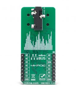
This table shows how the pinout on Audio Xover Click corresponds to the pinout on the mikroBUS™ socket (the latter shown in the two middle columns).
Onboard settings and indicators
Label | Name | Default | Description |
---|---|---|---|
PWR | LED GREEN | – | Power LED Indicator |
SL1 | LHP | Left | Left channel high pass cutoff frequency selector; Left: 120Hz |
SW1 | SLP | Left | Subwoofer channel low pass cutoff frequency selector; Middle: 90Hz |
SR1 | RHP | Left | Right channel high pass cutoff frequency selector; Right: 70Hz |
Audio Xover Click electrical specifications
Description | Min | Typ | Max | Unit |
---|---|---|---|---|
Supply Voltage | – | 5 | – | V |
Software Support
We provide a library for the Audio Xover Click on our LibStock page, as well as a demo application (example), developed using MIKROE compilers. The demo can run on all the main MIKROE development boards.
Library Description
Library contains function for enable and disable module.
Key functions:
void audioxover_set_mode( uint8_t state )
– This function set CS pin on 1 ( ENABLE ) and 0 ( DISABLE )
Examples description
The application is composed of three sections :
- System Initialization – Initializes all necessary GPIO pins
- Application Initialization – Initializes driver init
- Application Task – Enable and disable module every one seconds.
void application_task ( ) { mikrobus_logWrite( "***ENABLE****", _LOG_LINE ); audioxover_set_mode( AUDIOXOVER_ENABLE ); Delay_ms( 3000 ); mikrobus_logWrite( "***DISABLE****", _LOG_LINE ); audioxover_set_mode( AUDIOXOVER_DISABLE ); Delay_ms( 3000 ); }
The full application code, and ready to use projects can be found on our LibStock page.
Other MIKROE Libraries used in the example:
- LOG(UART) Library
Additional notes and informations
Depending on the development board you are using, you may need USB UART click, USB UART 2 click or RS232 click to connect to your PC, for development systems with no UART to USB interface available on the board. The terminal available in all MIKROE compilers, or any other terminal application of your choice, can be used to read the message.
mikroSDK
This Click board™ is supported with mikroSDK – MIKROE Software Development Kit. To ensure proper operation of mikroSDK compliant Click board™ demo applications, mikroSDK should be downloaded from the LibStock and installed for the compiler you are using.
For more information about mikroSDK, visit the official page.