How does it work?
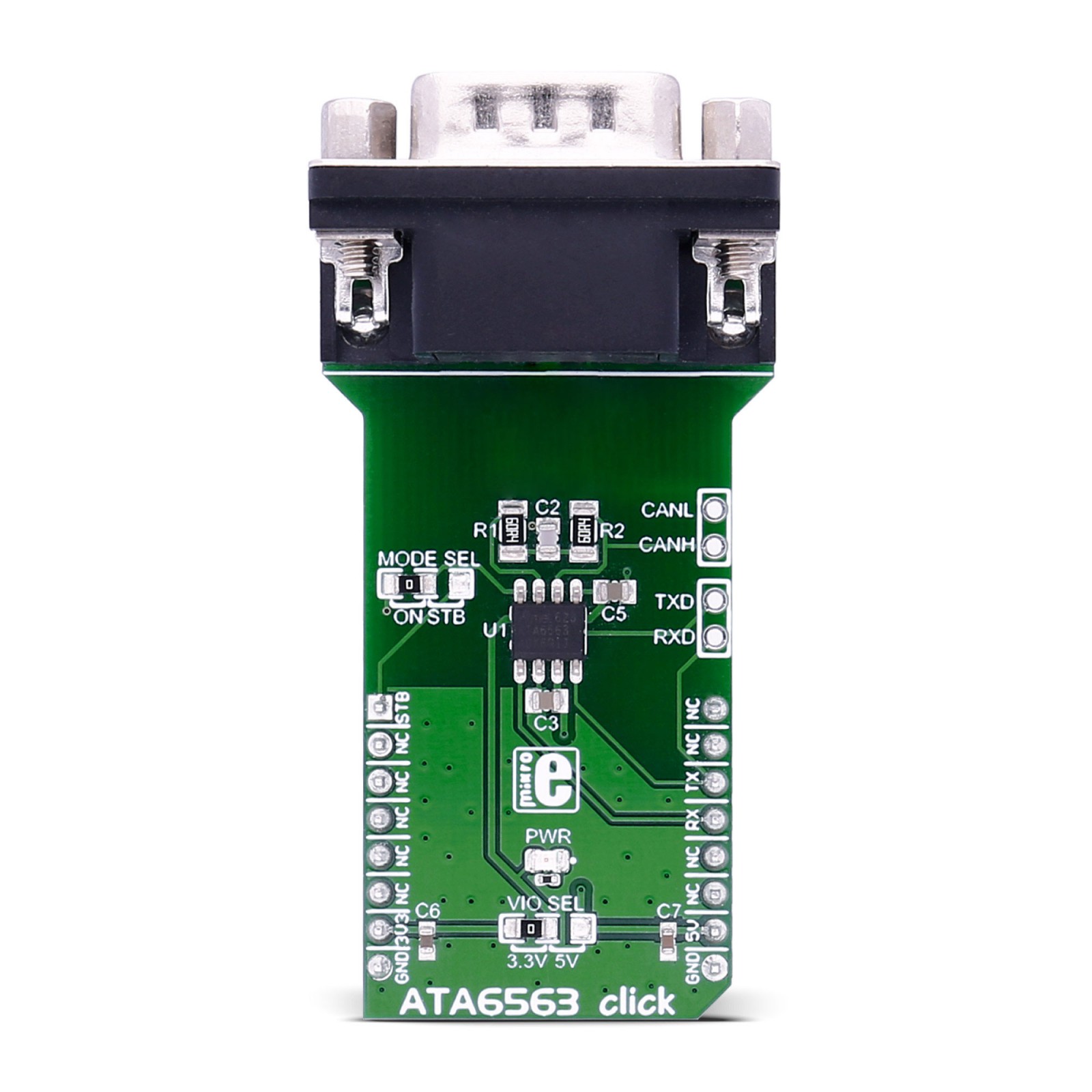
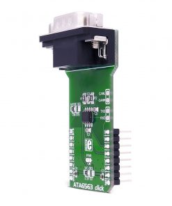
ATA6563 Click is based on the ATA6563, a high-speed CAN transceiver with standby mode from Microchip. It features low electromagnetic emission (EME), high electromagnetic immunity (EMI), remote wake-up capability, under-voltage detection, and more. The transceiver supports three operating modes: unpowered, standby, and normal. In normal mode, the ATA6563 can transmit and receive data via the CANH and CANL bus lines, where the high-speed comparator (HSC) converts the analog data on the bus lines into digital data. In standby mode, no transmission is available to reduce the current consumption. You can wake up the ATA6563 remotely over the CAN bus.
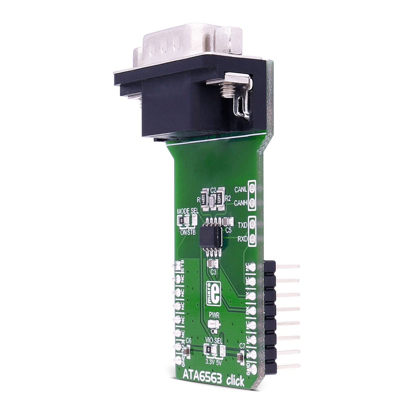
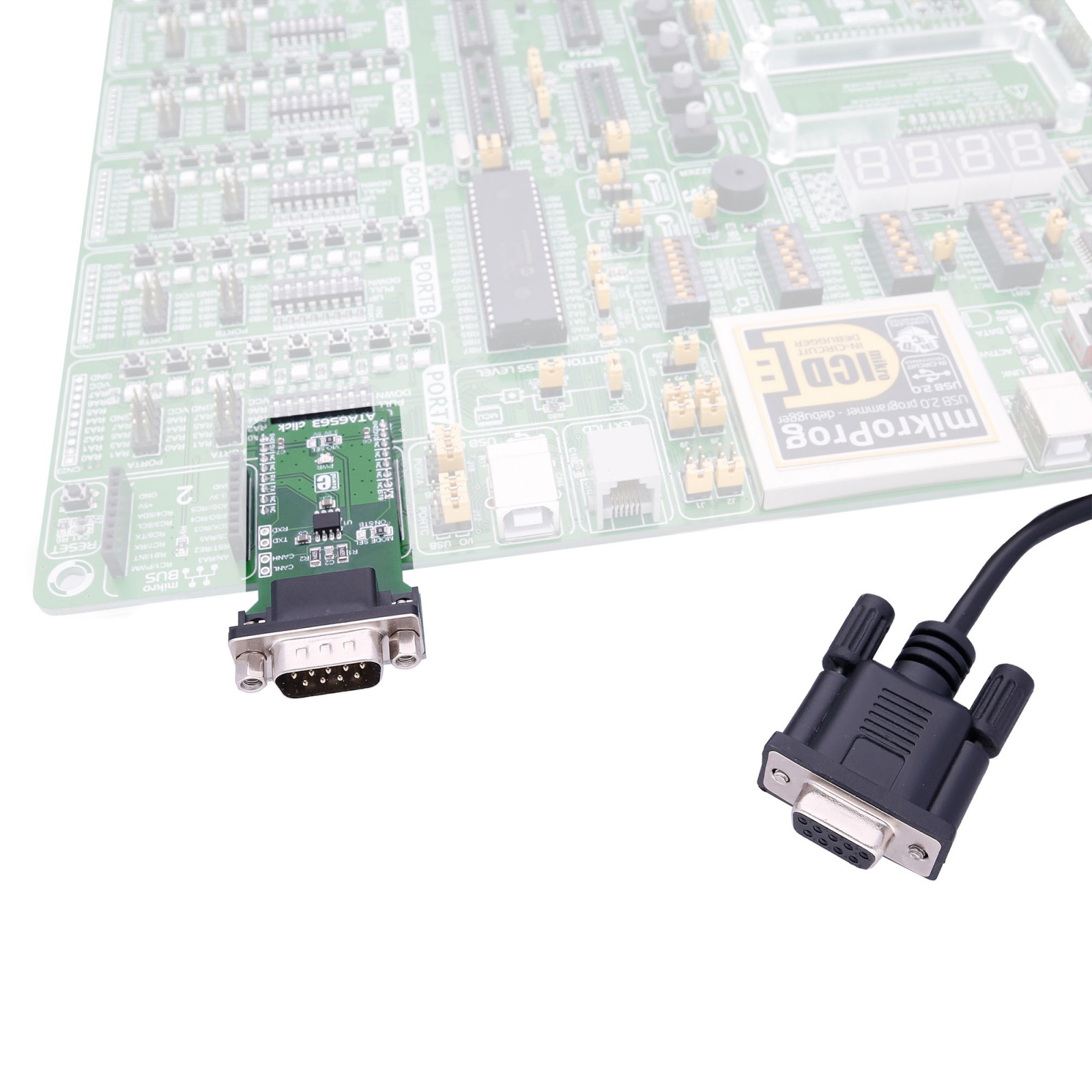
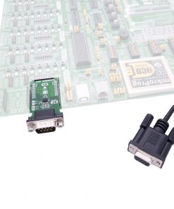
The transceiver is CAN FD (Flexible data rate) ready, meaning it has increased data rates compared to classic CAN. The ATA6563 Click is equipped with an RS232 connector, but you can also use a direct approach to the CAN and UART pins for testing purposes. There is a MODE SEL jumper over which you can set the behavior of the ATA6563 Click. It is set to ON by default, which means it is set for normal mode of operation. You can choose the STB position and control the operating modes by the host MCU over the mikroBUS™ socket.
ATA6563 Click uses a standard 2-Wire UART interface to communicate with the host MCU. In addition, if enabled over the MODE SEL jumper, you can use the STB pin to control the operating modes of the transceiver by the software.
This Click board™ can operate with either 3.3V or 5V logic voltage levels selected via the VIO SEL jumper. This way, both 3.3V and 5V capable MCUs can use the communication lines properly. However, the Click board™ comes equipped with a library containing easy-to-use functions and an example code that can be used as a reference for further development.
Specifications
Type
CAN,CAN FD
Applications
Can be used for the development of classical CAN and CAN FD networks in automotive, industrial, aerospace, medical, and consumer applications
On-board modules
ATA6563 – high-speed CAN transceiver with standby mode from Microchip
Key Features
Optimized for CAN FD at 2 and 5Mbps operation, maximum propagation delay of 210ns, support for CAN 2.0, and CAN with flexible data rates, low electromagnetic emission, high electromagnetic immunity, remote wake-up, high electrostatic discharge, and more
Interface
UART
Feature
No ClickID
Compatibility
mikroBUS™
Click board size
L (57.15 x 25.4 mm)
Input Voltage
3.3V or 5V
Pinout diagram
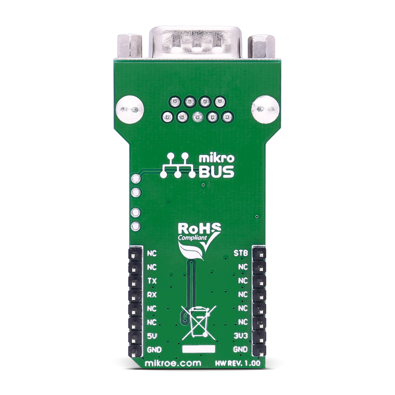
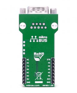
This table shows how the pinout on ATA6563 Click corresponds to the pinout on the mikroBUS™ socket (the latter shown in the two middle columns).
Onboard settings and indicators
Label | Name | Default | Description |
---|---|---|---|
– | PWR | – | Power LED Indicator |
– | VIO SEL | Left | Logic Level Voltage Selection 3V3/5V: Left position 3V3, Right position 5V |
– | MODE SEL | Left | Operating Mode Selection ON/STB: Left position ON, Right position STB |
ATA6563 Click electrical specifications
Description | Min | Typ | Max | Unit |
---|---|---|---|---|
Supply Voltage | 3.3 | – | 5 | V |
Communication Speed | – | – | 5 | Mbps |