How does it work?
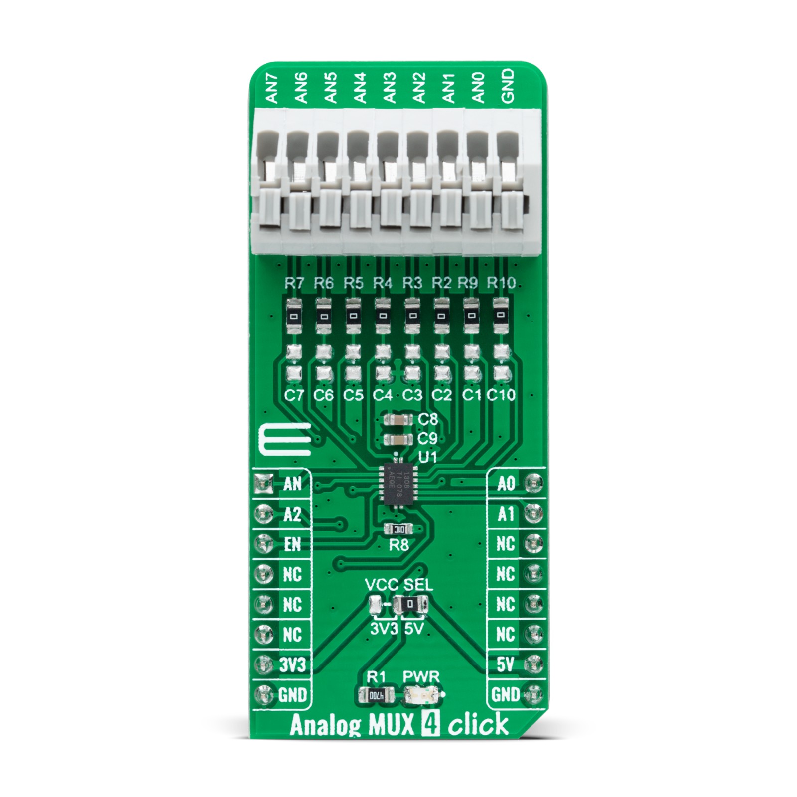
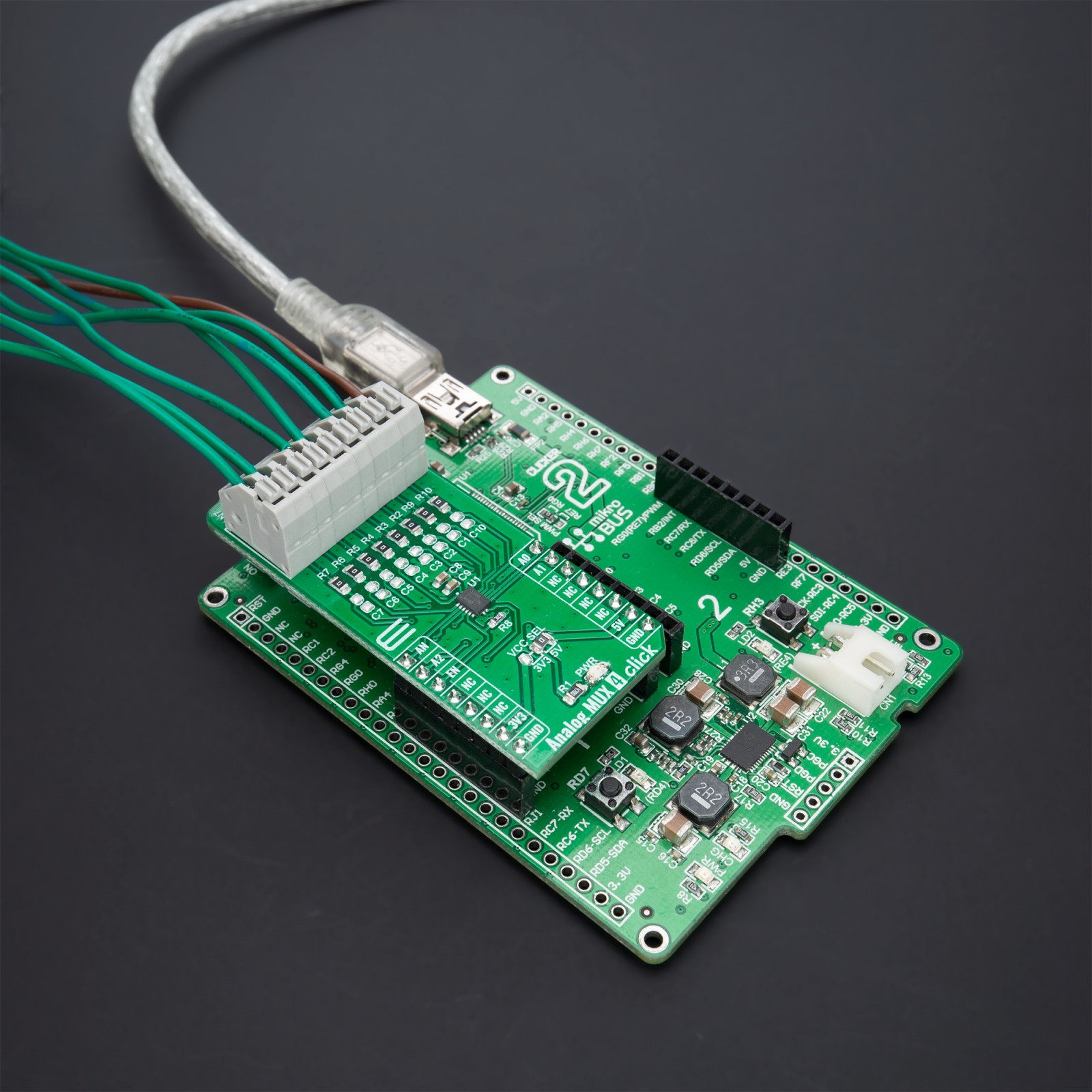
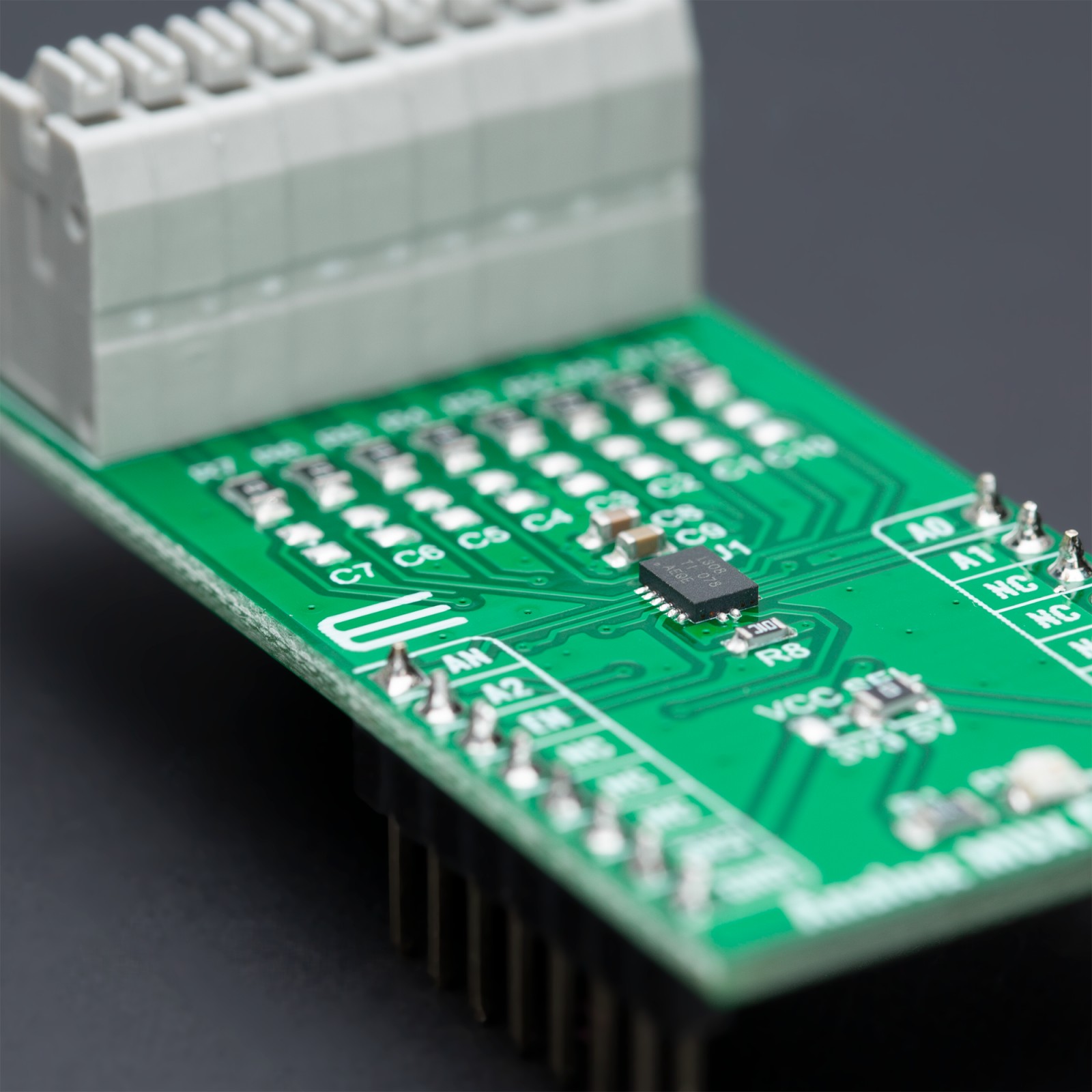
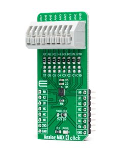
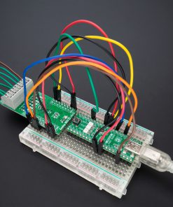
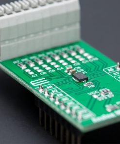
Analog MUX 4 Click as its foundation uses the TMUX1308, a general-purpose 8:1 single-ended CMOS analog multiplexer from Texas Instruments. The TMUX1308 multiplexer allows for multiple inputs/sensors to be monitored with a single AN pin of the mikroBUS™ socket supporting bidirectional analog and digital signals ranging from 0 to 5V. It has an internal injection current control eliminating the need for external diode and resistor networks to protect the switch, keeping the input signals within the supply voltage. The internal injection current control circuitry allows signals on disabled signal paths to exceed the supply voltage without affecting the signal of the enabled signal path.
Alongside internal injection current control, the TMUX1308 also has another protection feature, called Break-before-make delay, which represents a safety feature preventing two inputs from connecting when the device is switching. The output first breaks from the ON-state switch before connecting with the next ON-state switch. This time delay between the break and the make is known as the break-before-make delay.
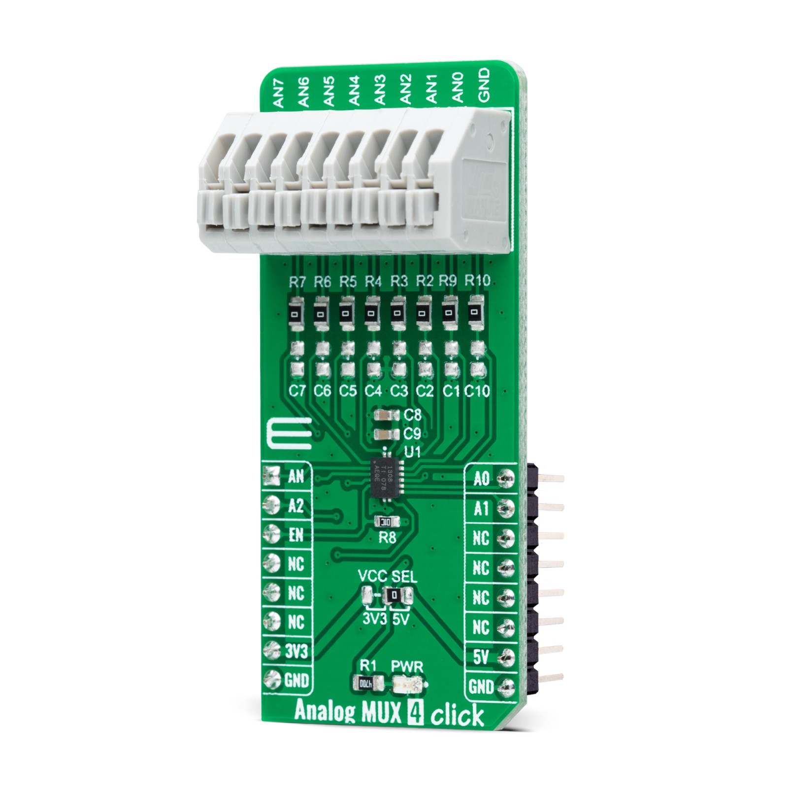
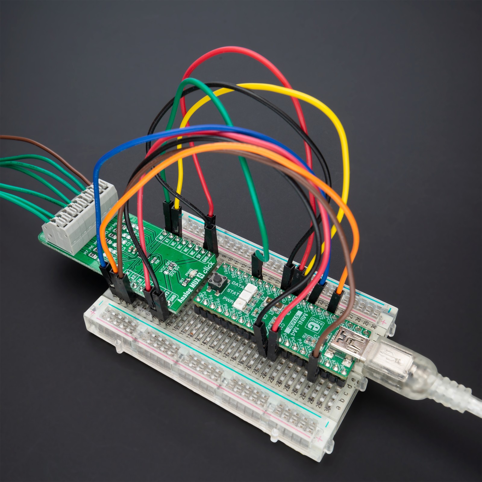
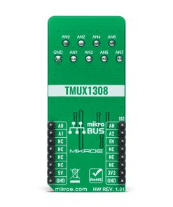
This Click board™ communicates with MCU using several GPIO pins. It can be enabled or disabled through the EN pin routed to the CS pin of the mikroBUS™ socket; hence, offering a switch operation to turn ON/OFF power delivery to the TMUX1308. It also provides three address signals, labeled from A0 to A2 and routed to the PWM, INT, and RST pins of the mikroBUS™ socket, that control the switch configuration and determine the activation of the desired analog input channel based on their setup. Also, each analog input has a jumper for its hardware activation or deactivation and capacitors for additional filtering of the input channels.
This Click board™ can operate with both 3.3V and 5V logic voltage levels selected via the VCC SEL jumper. This way, it is allowed for both 3.3V and 5V capable MCUs to use the communication lines properly. However, the Click board™ comes equipped with a library containing easy-to-use functions and an example code that can be used, as a reference, for further development.
Specifications
Type
Measurements,Port expander
Applications
Can be used for various applications, from industrial to instrumentation, consumer, communications, and more
On-board modules
TMUX1308 – general-purpose 8:1 single-ended CMOS analog multiplexer from Texas Instruments
Key Features
Injection current control, back-powering protection, bidirectional signal path, Break-Before-Make switching, VCC range signal handling, TTL/CMOS-logic compatible, pin-controllable, and more
Interface
Analog,GPIO
Feature
No ClickID
Compatibility
mikroBUS™
Click board size
L (57.15 x 25.4 mm)
Input Voltage
3.3V or 5V
Pinout diagram
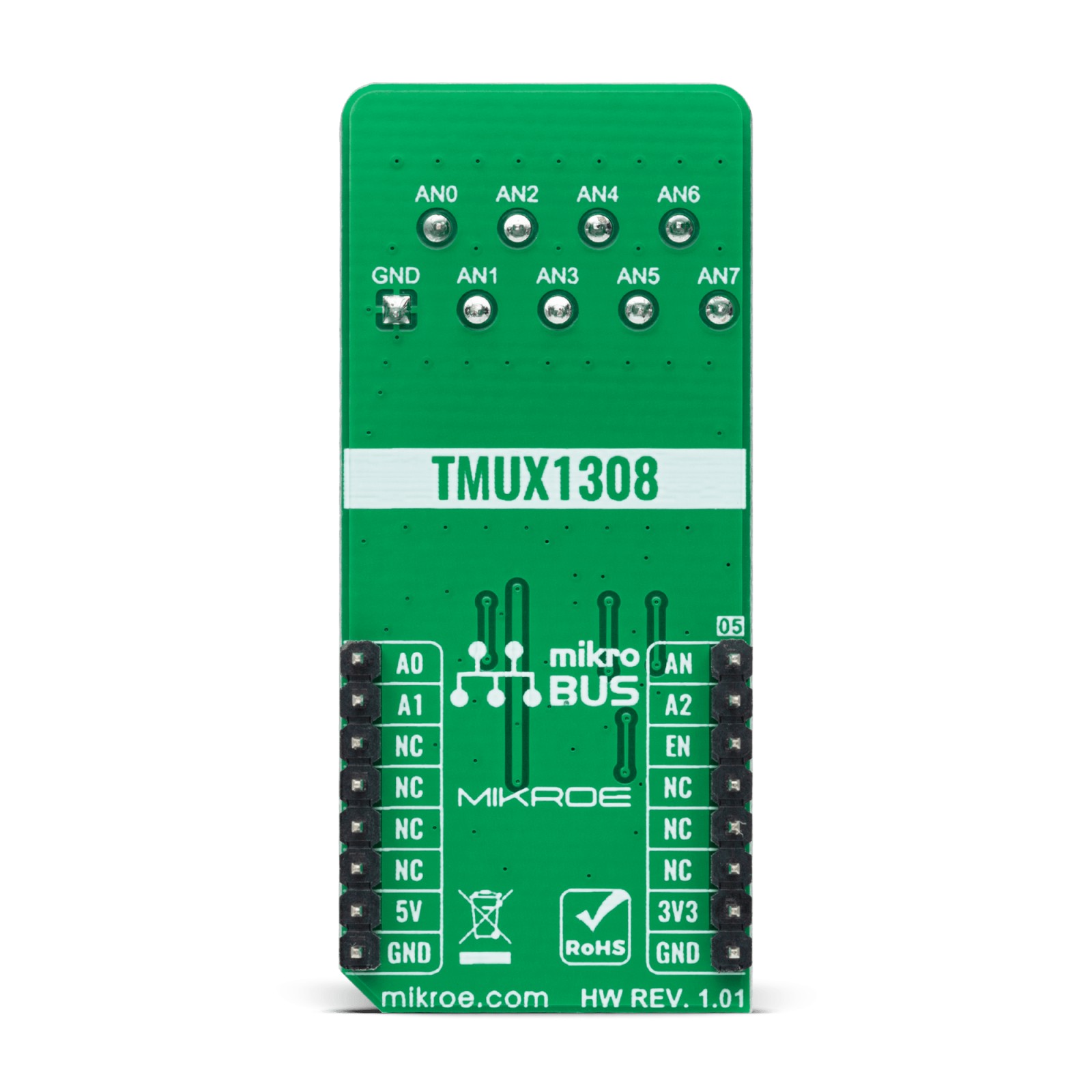
This table shows how the pinout on Analog MUX 4 Click corresponds to the pinout on the mikroBUS™ socket (the latter shown in the two middle columns).
Onboard settings and indicators
Label | Name | Default | Description |
---|---|---|---|
LD1 | PWR | – | Power LED Indicator |
JP1 | VCC SEL | Right | Logic Level Voltage Selection 3V3/5V: Left position 3V3, Right position 5V |
Analog MUX 4 Click electrical specifications
Description | Min | Typ | Max | Unit |
---|---|---|---|---|
Supply Voltage | 3.3 | – | 5 | V |
Analog Input Range | 0 | – | 5 | V |
ON-State Resistance | – | – | 195 | Ω |
Operating Temperature Range | -40 | 25 | +120 | °C |
Software Support
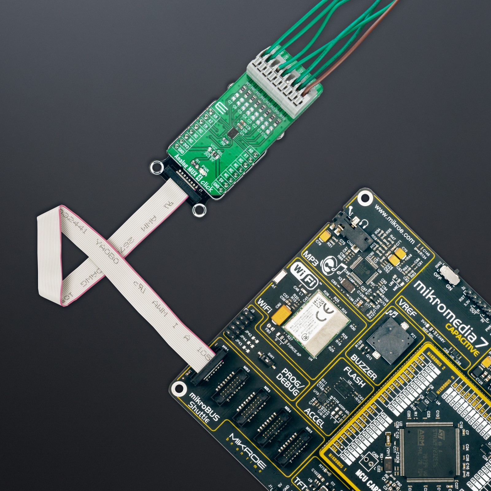
We provide a library for the Analog MUX 4 Click as well as a demo application (example), developed using MikroElektronika compilers. The demo can run on all the main MikroElektronika development boards.
Package can be downloaded/installed directly from NECTO Studio Package Manager(recommended way), downloaded from our LibStock™ or found on Mikroe github account.
Library Description
This library contains API for Analog MUX 4 Click driver.
Key functions
-
analogmux4_enable_input
This function enables analog inputs. -
analogmux4_read_an_pin_voltage
This function reads results of AD conversion of the AN pin and converts them to proportional voltage level. -
analogmux4_set_input_channel
This function sets the analog input channel.
Example Description
This example demonstrates the use of Analog MUX 4 Click board™.
void application_task ( void ) { float analogmux4_an_voltage = 0; for ( uint8_t cnt = ANALOGMUX4_CHANNEL_0; cnt <= ANALOGMUX4_CHANNEL_7; cnt++ ) { analogmux4_set_input_channel ( &analogmux4, cnt ); if ( ADC_ERROR != analogmux4_read_an_pin_voltage ( &analogmux4, &analogmux4_an_voltage ) ) { log_printf( &logger, " AN%u voltage : %.3f Vrn", ( uint16_t ) cnt, analogmux4_an_voltage ); } } log_printf( &logger, "rn" ); Delay_ms( 1000 ); }
The full application code, and ready to use projects can be installed directly from NECTO Studio Package Manager(recommended way), downloaded from our LibStock™ or found on Mikroe github account.
Other Mikroe Libraries used in the example:
- MikroSDK.Board
- MikroSDK.Log
- Click.Flash10
Additional notes and informations
Depending on the development board you are using, you may need USB UART click, USB UART 2 Click or RS232 Click to connect to your PC, for development systems with no UART to USB interface available on the board. UART terminal is available in all MikroElektronika compilers.
mikroSDK
This Click board™ is supported with mikroSDK – MikroElektronika Software Development Kit. To ensure proper operation of mikroSDK compliant Click board™ demo applications, mikroSDK should be downloaded from the LibStock and installed for the compiler you are using.
For more information about mikroSDK, visit the official page.