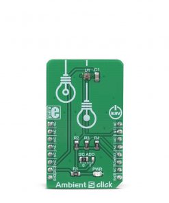
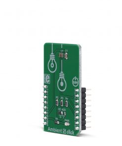
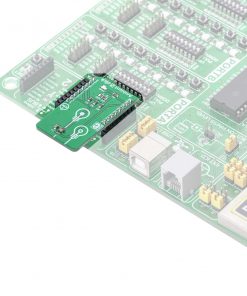
Ambient 5 Click
R230.00 ex. VAT
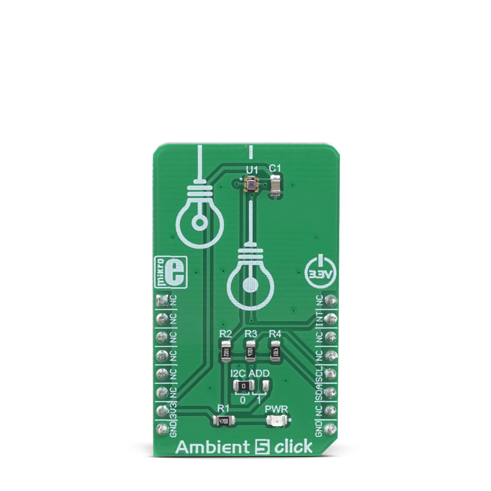
Ambient 5 click can sense the intensity of the ambient light, providing measurement data in a digital format, over the I2C interface. It utilizes the VEML6030, a miniature ambient light sensor (ALS) which occupies only 2×2 mm of space. Packed in a small transparent casing, this sensor offers a lot of features. Thanks to its 16-bit dynamic range, it can be used in very dim, but also in very bright lighting conditions. A Filtron™ technology provides spectral response close to a real human eye. The flicker noise rejection algorithm improves accuracy, while excellent thermal compensation ensures consistent readings.
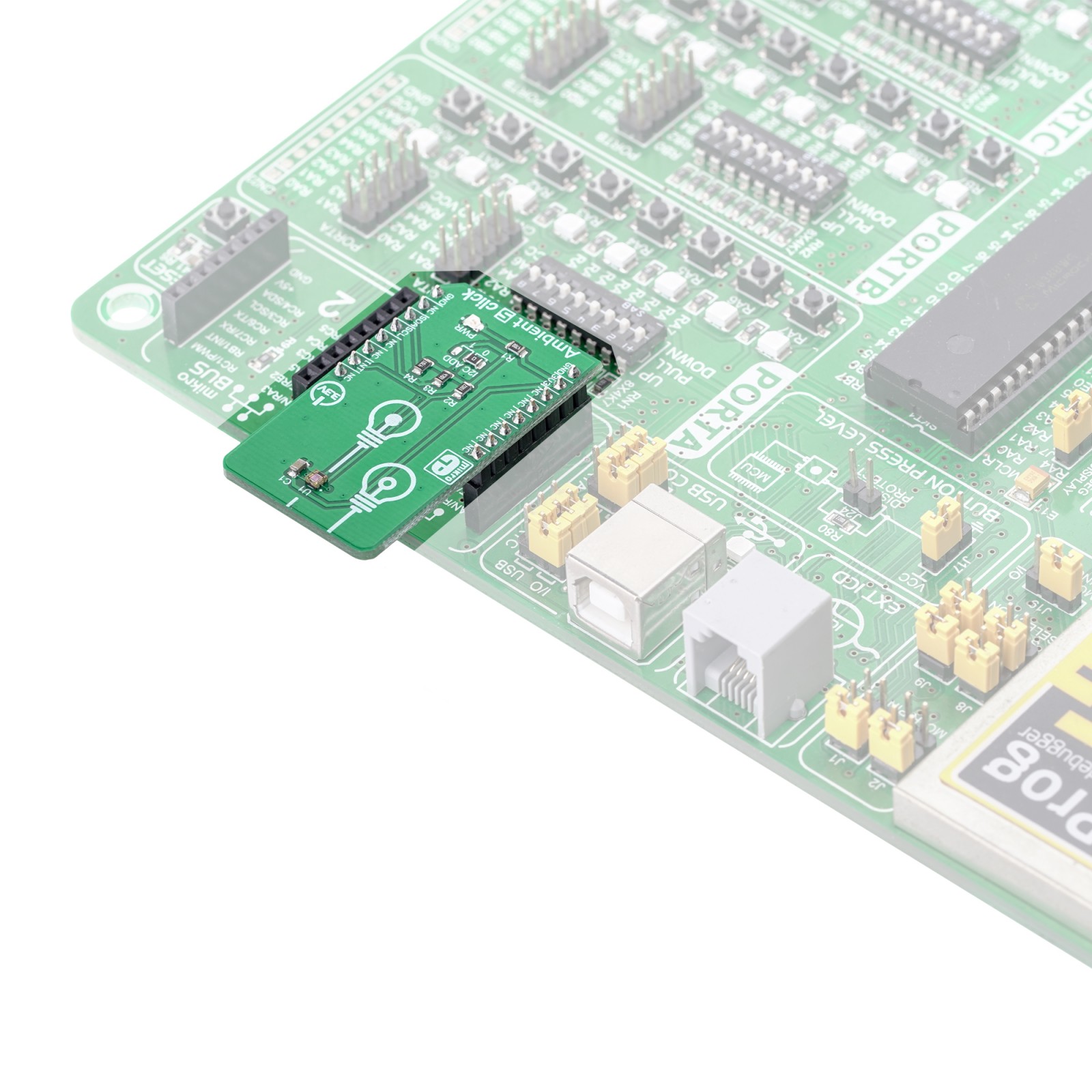
Ambient 5 click is supported by a mikroSDK compliant library, which includes functions that simplify software development. This Click board™ comes as a fully tested product, ready to be used on a system equipped with the mikroBUS™ socket.
Stock: Lead-time applicable.
| 5+ | R218.50 |
| 10+ | R207.00 |
| 15+ | R195.50 |
| 20+ | R188.14 |
Thanks to the used proprietary technologies that allow high precision, reliability, and low power consumption, Ambient 5 Click can be used for a rapid development of various cost-effective applications that rely on light intensity sensing, including optical switches, screen dimming applications for mobile and handheld devices, light metering applications (lux meters), and similar.
How does it work?
The main component of the Ambient 5 click is the VEML6030, a high accuracy ambient light sensor (ALS) with I2C interface, from Vishay Semiconductors. This sensor utilizes several proprietary technologies to ensure accurate measurements of the light intensity, with the spectral response very close to a human eye. By utilizing a sensitive photo-diode, low noise amplifier, and a 16-bit A/D converter (ADC), this sensor can provide the data directly, with no need for complex calculations. The dynamic range for the ambient light sensor is very large, starting down from 0 lx up to about 120 klx, with the maximum resolution of only 0.0036 lx/count. The extremely high sensitivity along with the linear response to different light sources, allows this sensor to be placed behind a dark glass or panels made of other semi-transparent materials.

The VEML6030 sensor has only six 16-bit registers, which make it very simple to configure and use. Even though, it comes with the mikroSDK compatible library, which simplifies the development even more. However, more detailed explanation of each command can be found in the datasheet of the VEML6030, if required.
A selectable GAIN allows a very wide dynamic range for the ALS measurement. There are two ALS_GAIN bits, allowing the gain level to be set to 1/4x, 1/2x, 1x, and 2x. This offers four different luminosity ranges to be covered for each selected integration time (ALS_IT). For example: the fastest integration time (25ms) results in the lowest resolution (1.8432 lx/count), and combined with the gain of 1/8x, it allows the highest luminosity value to be measured (120,796 lx)
Power consumption of the VEML6030 is in tight relation with the programmed integration time, power supply, and amplification. There are two bits available to select the power mode (PSM), four bits to select the integration time (ALS_IT), and two bits to select the gain (ALS_GAIN). These parameters are determining factors for the average power consumption, measurement resolution, and refresh time. By utilizing a such a flexible power saving scheme, the VEML6030 can be adapted to any type of power sensitive application.
A configurable interrupt engine allows optimized firmware to be developed, avoiding polling routines and frequent access over the I2C interface. The interrupt pin (INT) is an open drain output, which is pulled to a HIGH logic level when it is not asserted. When any of the programmed light thresholds is exceeded for a programmed number of times, an interrupt event will be generated, asserting this pin to a LOW logic level. The interrupt pin is routed to the mikroBUS™ INT pin.
The slave I2C address of the VEML6030 can be selected by switching the SMD jumper to an appropriate position. Unlike some other devices, this jumper does not set the LSB of the I2C address, but rather selects between two possible values: when tied to GND (0), the I2C address of the VEML6030 will be 0b0010000x. When tied to VCC (1), the I2C address will be 0b1001000x. The x is the I2C address R/W byte. Due to maximum electrical ratings, this Click board™ is to be used with 3.3V MCUs, only.
Specifications
Type
Optical
Applications
This sensor is an ideal solution for both the IoT light sensing applications, but also for portable or handheld devices which utilize an accurate light intensity sensing, such as the TFT/LCD screens, keypad backlight, cell phones, digital cameras, and similar
On-board modules
VEML6030, a high accuracy ambient light sensor (ALS) with I2C interface, from Vishay Semiconductors
Key Features
High resolution and range of light intensity that can be measured, spectral response similar to human eye, low power consumption, compact design ideal for building IoT applications, immune to flickering and fluorescent light sources, independent of the light source type, and more
Interface
I2C
Feature
No ClickID
Compatibility
mikroBUS™
Click board size
M (42.9 x 25.4 mm)
Input Voltage
3.3V
Pinout diagram
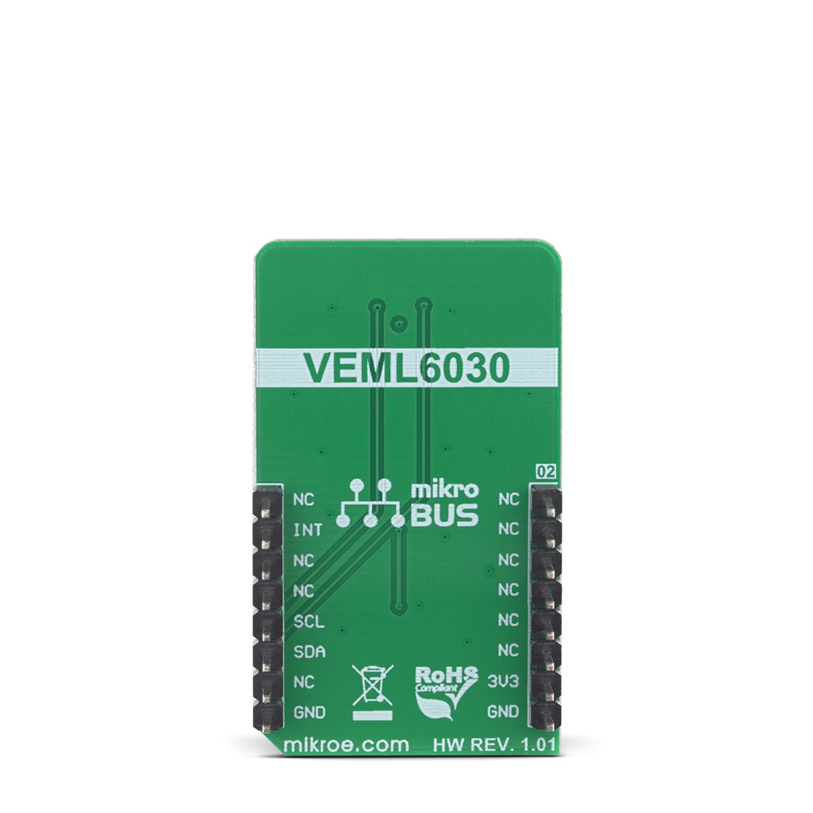
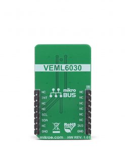
This table shows how the pinout on Ambient 5 Click corresponds to the pinout on the mikroBUS™ socket (the latter shown in the two middle columns).
Onboard settings and indicators
| Label | Name | Default | Description |
|---|---|---|---|
| LD1 | PWR | – | Power LED indicator |
| JP1 | I2C ADD | Left | I2C slave address selection: left position tied to GND (0), right position tied to VCC (1) |
Software support
We provide a library for the Ambient 5 Click on our LibStock page, as well as a demo application (example), developed using MikroElektronika compilers. The demo can run on all the main MikroElektronika development boards.
Library Description
Library contains functions for reading from and writing to selected registers Library contains functions for calculating refresh time, data resolution and light level Library contains functions for powering device on and checking state of int pin Library contains functions for setting high and low threshold values.
Key functions:
void ambient5_powerOn( void )– Fpowers device on and sets basic settings.float ambient5_getHighResolutionLightLevel( void )– returns ambient light level in lux [lx].uint16_t ambient5_getRefreshTime( void )– returns time needed for new data to become available.
Examples description
The application is composed of the three sections :
- System Initialization – Initializes i2c, log, and INT pin as input.
- Application Initialization – Initializes i2c driver, powers the device and calculates refresh time.
- Application Task – Logs high resolution data after a period of time ( refresh time calculated using – ambient5_getRefreshTime( ) ).
void applicationTask( )
{
    for (i = 0; i < rTime; i ++)
    {
        Delay_ms(1);
    }

    highResLightLevel = ambient5_getHighResolutionLightLevel( );

    FloatToStr( highResLightLevel, text );

    mikrobus_logWrite( " Ambient Light Level :   ", _LOG_TEXT );
    mikrobus_logWrite( text, _LOG_TEXT );
    mikrobus_logWrite( "  lx", _LOG_LINE );
}
The full application code, and ready to use projects can be found on our LibStock page.
Other mikroE Libraries used in the example:
I2CUARTConversions
Additional notes and informations
Depending on the development board you are using, you may need USB UART click, USB UART 2 click or RS232 click to connect to your PC, for development systems with no UART to USB interface available on the board. The terminal available in all MikroElektronika compilers, or any other terminal application of your choice, can be used to read the message.
Resources
Downloads
| Weight | 18 g |
|---|---|
| Brand | MikroElektronika |

