How does it work?
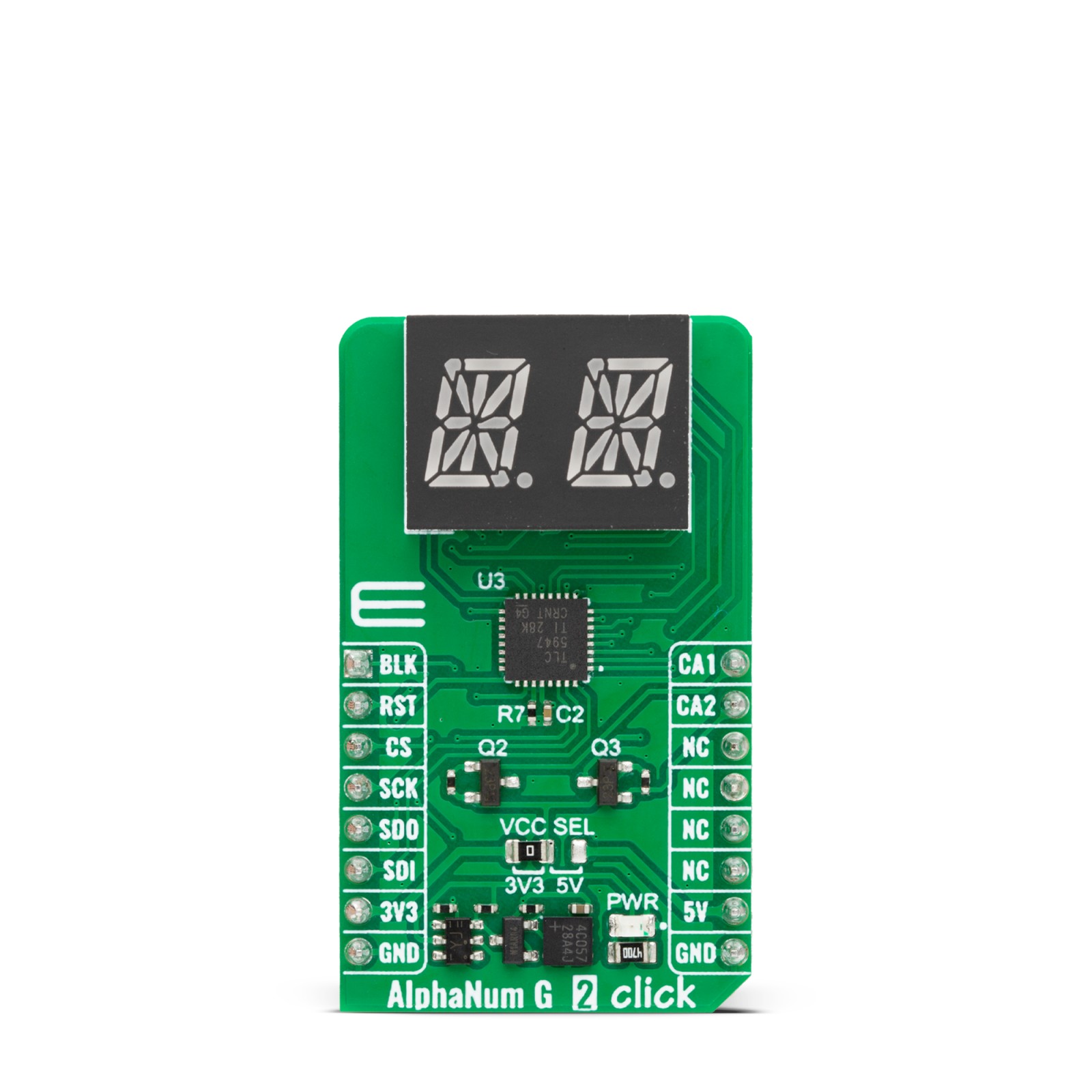
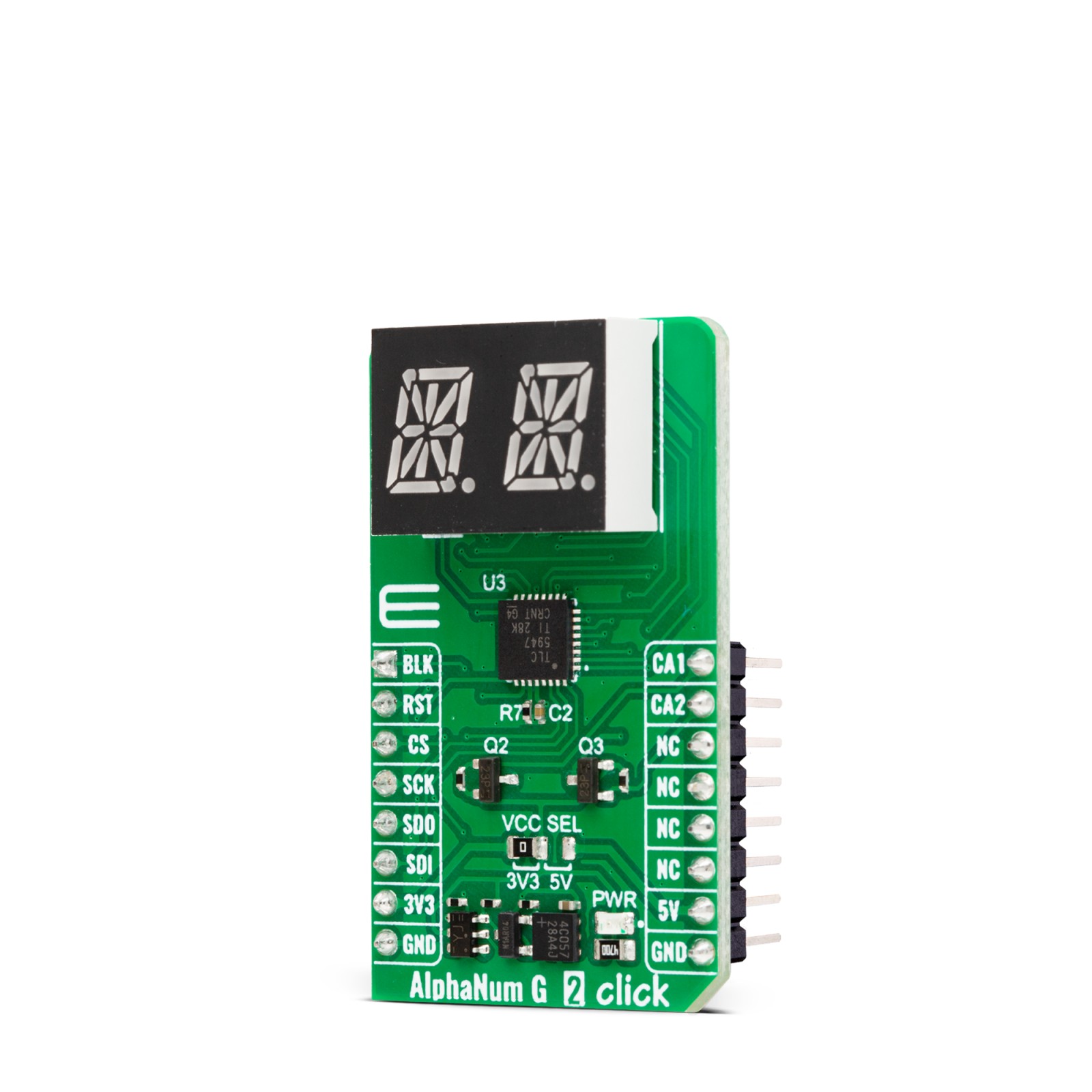
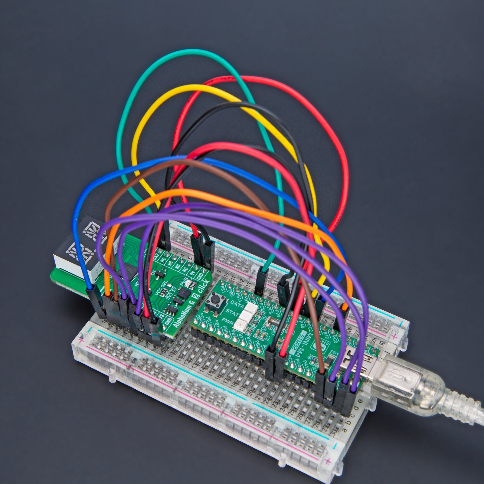
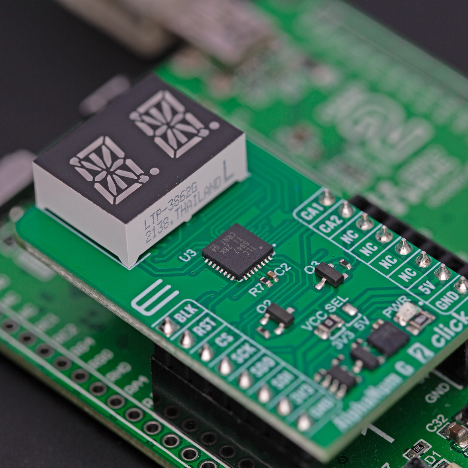
AlphaNum G 2 Click is based on the LTP-3862, a dual-digit 16-segment alphanumeric green display from Lite-ON. It has a 75mW of power disipation per segment. The TLC5947, a 24-channel 12-bit PWM LED driver from Texas Instruments, drives all these LED segments. It is a constant current sink LED driver with adjustable 4096 pulse width modulation (PWM) on each channel individually. The PWM control is repeated automatically with the programmed grayscale data. An external resistor sets the constant current to around 10mA. The LED driver features thermal shutdown, auto display repeat, noise reduction, and more.
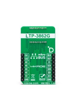
AlphaNum G 2 Click uses a standard 4-Wire SPI serial interface to communicate with the host MCU, supporting a clock frequency of up to 30MHz. A Blank BLK pin can turn all constant current outputs to OFF while initializing the grayscale PWM timing. This can be achieved by writing the High logic state on the Blank pin. You can also turn off every display separately, no matter the LED driver IC, over the CA1 and CA2 pins. Those pins control the common anode pins of the displays.
This Click board™ can operate with either 3.3V or 5V logic voltage levels selected via the VCC SEL jumper. This way, both 3.3V and 5V capable MCUs can use the communication lines properly. Also, this Click board™ comes equipped with a library containing easy-to-use functions and an example code that can be used as a reference for further development.
Specifications
Type
LED Segment
Applications
Can be used for the development of applications that require a visible display or others that display numerical/textual information
On-board modules
LTP-3862 – dual-digit 16-segment alphanumeric green display from Lite-ON
Key Features
Double 16-segment green display with a decimal point, continuous uniform segments, low power requirement, excellent character appearance, wide viewing angle, categorized for luminous intensity, and more
Interface
SPI
Feature
ClickID
Compatibility
mikroBUS™
Click board size
M (42.9 x 25.4 mm)
Input Voltage
3.3V or 5V
Pinout diagram
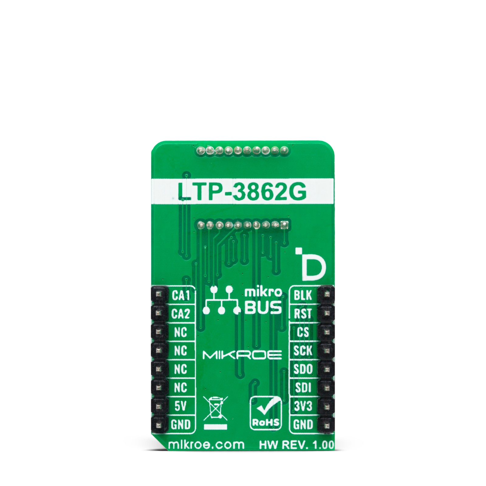
This table shows how the pinout on AlphaNum G 2 Click corresponds to the pinout on the mikroBUS™ socket (the latter shown in the two middle columns).
Onboard settings and indicators
Label | Name | Default | Description |
---|---|---|---|
LD1 | PWR | – | Power LED Indicator |
JP1 | VCC SEL | Left | Power/Logic Voltage Level Selection 3V3/5V: Left position 3V3, Right position 5V |
AlphaNum G 2 Click electrical specifications
Description | Min | Typ | Max | Unit |
---|---|---|---|---|
Supply Voltage | 3.3 | – | 5 | V |
Software Support
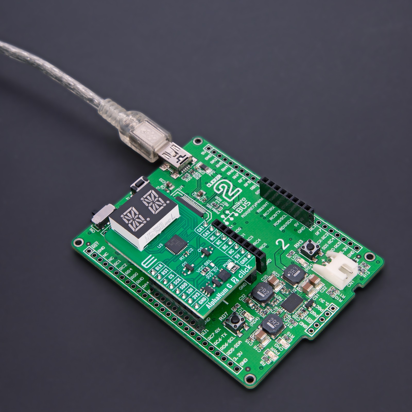
We provide a library for the AlphaNum G 2 Click as well as a demo application (example), developed using MIKROE compilers. The demo can run on all the main MIKROE development boards.
Package can be downloaded/installed directly from NECTO Studio Package Manager (recommended), downloaded from our LibStock™ or found on Mikroe github account.
Library Description
This library contains API for AlphaNum G 2 Click driver.
Key functions
-
alphanumg2_display_character
AlphaNum G 2 display character function. -
alphanumg2_set_led_output
AlphaNum G 2 set LED output function.
Example Description
This example demonstrates the use of the AlphaNum G 2 Click board™ by writing and displaying the desired alphanumeric characters.
void application_task ( void )
{
log_printf( &logger, " %c %crn", character, character + 1 );
if ( ALPHANUMG2_OK == alphanumg2_display_character( &alphanumg2,
character, ALPHANUMG2_BRIGHTNESS_MAX,
character + 1, ALPHANUMG2_BRIGHTNESS_MAX ) )
{
character++;
if ( ASCII_CHARACTER_UPPERCASE_Z <= character )
{
character = ASCII_CHARACTER_DIGIT_0;
log_printf( &logger, "------------------------rn" );
Delay_ms( 1000 );
}
}
}
The full application code, and ready to use projects can be installed directly from NECTO Studio Package Manager (recommended), downloaded from our LibStock™ or found on Mikroe github account.
Other Mikroe Libraries used in the example:
- MikroSDK.Board
- MikroSDK.Log
- Click.AlphaNumG2
Additional notes and informations
Depending on the development board you are using, you may need USB UART click, USB UART 2 Click or RS232 Click to connect to your PC, for development systems with no UART to USB interface available on the board. UART terminal is available in all MIKROE compilers.
mikroSDK
This Click board™ is supported with mikroSDK – MIKROE Software Development Kit. To ensure proper operation of mikroSDK compliant Click board™ demo applications, mikroSDK should be downloaded from the LibStock and installed for the compiler you are using.
For more information about mikroSDK, visit the official page.