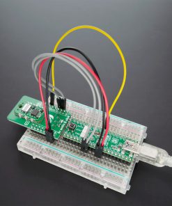
Air quality 7 Click
R1,250.00 ex. VAT
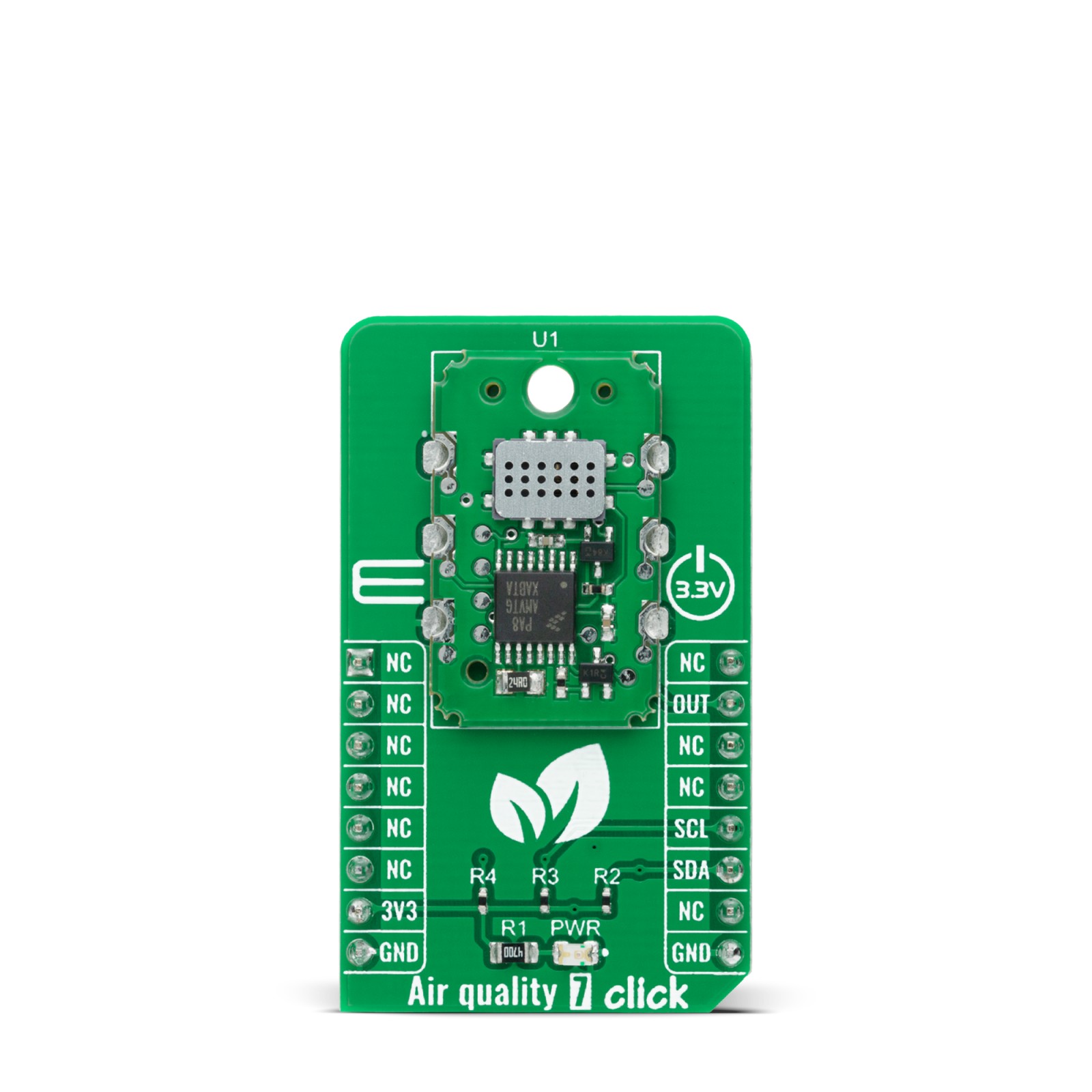
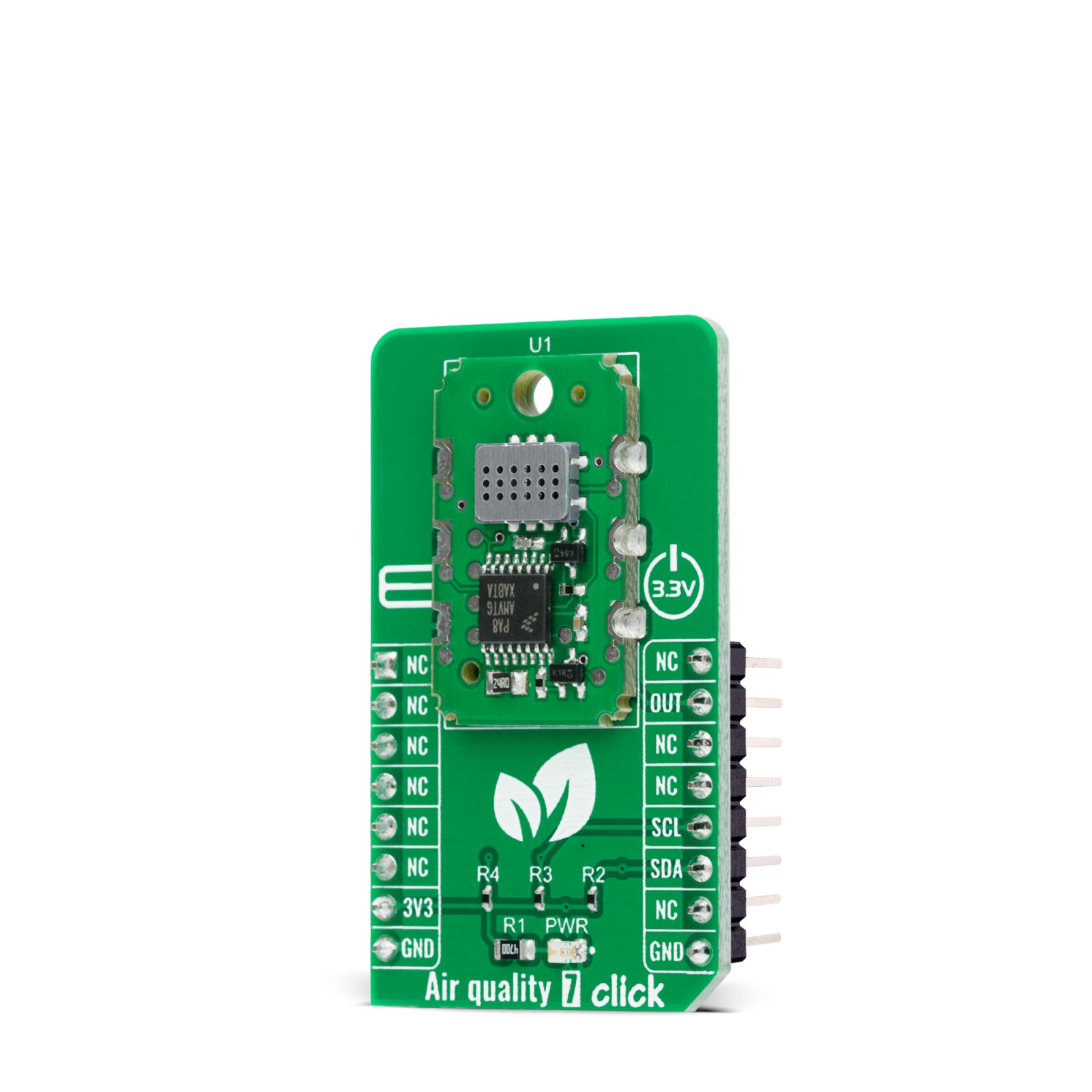
Air quality 7 Click is a compact add-on board that combines state-of-the-art MOS sensor technology with intelligent detection algorithms to monitor VOCs and CO2 equivalent variations in confined spaces. This board features the MiCS-VZ-89TE, an integrated sensor module for indoor air quality monitoring from Amphenol. This Click board™, an I2C configurable environmental sensor board, has many features such as low power, wide VOCs detection range, high sensitivity, and high resistance to shocks and vibrations which make it an excellent choice for VOC and CO2 monitoring in confined spaces such as meeting rooms and vehicle cabins, saving energy and reducing cost-of-ownership.
Air quality 7 Click is supported by a mikroSDK compliant library, which includes functions that simplify software development. This Click board™ comes as a fully tested product, ready to be used on a system equipped with the mikroBUS™ socket.
Stock: Lead-time applicable.
| 5+ | R1,187.50 |
| 10+ | R1,125.00 |
| 15+ | R1,062.50 |
| 20+ | R1,022.50 |
How does it work?
Air quality 7 Click is based on the MiCS-VZ-89TE, an integrated sensor module for indoor air quality monitoring from Amphenol. The MiCS-VZ-89TE combines the most modern MOS sensor technology with intelligent detection algorithms to control VOCs and CO2 fluctuations in buildings. Among some other appealing features like 3.3V supply, I2C communication, and calibration-free high sensitivity this module has a characteristic a small size factor. The sensor must not be exposed to high concentrations of organic solvents, ammonia, silicone vapor, or cigarette-smoke to avoid poisoning the sensitive layer. It should be protected against water and dust projections, and its Vendor strongly recommends using ESD protection equipment to handle the sensor.

This Click board™ is easy to program and read data because it does not require an overly demanding configuration. The first step is the initialization of all the necessary peripherals and pins. The additional delay time of a couple of seconds during system initialization is needed because this Click board™ needs some time to establish the measurements. The second initialization is the I2C driver and communication test by reading the revision information of the module. If the CRC check is OK it allows the program to go on, and if it’s not OK, a user needs to restart the program. If every step is valid, the user can read the air quality status. This can also be seen in an example code that contains easy to use functions that may be used as a reference for further development.
Air quality 7 Click communicates with MCU using the standard I2C 2-Wire interface that supports Standard-Mode operation with a bit rates up to 100 kbit/s. The MiCS-VZ-89TE slave address contains seven fixed bits. The slave address byte is the first byte received following the START condition from the Master device. The first part of the address byte consists of a 4-bit device code which is set to 1110 for the IAQS followed by three address bits (A2, A1, A0) which are programmed at 0. The dual signal output routed on the OUT pin of the mikroBUS™ socket, which brings the results of the measurements, can be read through a multiplexed PWM output or an I2C bus.
This Click board™ is designed to be operated only with a 3.3V logic voltage level. A proper logic voltage level conversion should be performed before the Click board™ is used with MCUs with different logic voltage levels. More information about the MiCS-VZ-89TE can be found in the attached datasheet. However, the Click board™ comes equipped with a library that contains easy to use functions and a usage example that may be used as a reference for further development.
Specifications
Type
Air Quality,Gas
Applications
Can be used for a VOC and CO2 monitoring in confined spaces such as meeting rooms and vehicle cabins, saving energy and reducing cost-of-ownership.
On-board modules
Air Quality 7 Click is based on the MiCS-VZ-89TE, an integrated sensor module for indoor air quality monitoring from Amphenol.
Key Features
Low power consumption, wide VOC detection range, high sensitivity, high resistance to shocks and vibrations, and more.
Interface
I2C
Feature
No ClickID
Compatibility
mikroBUS™
Click board size
M (42.9 x 25.4 mm)
Input Voltage
3.3V
Pinout diagram
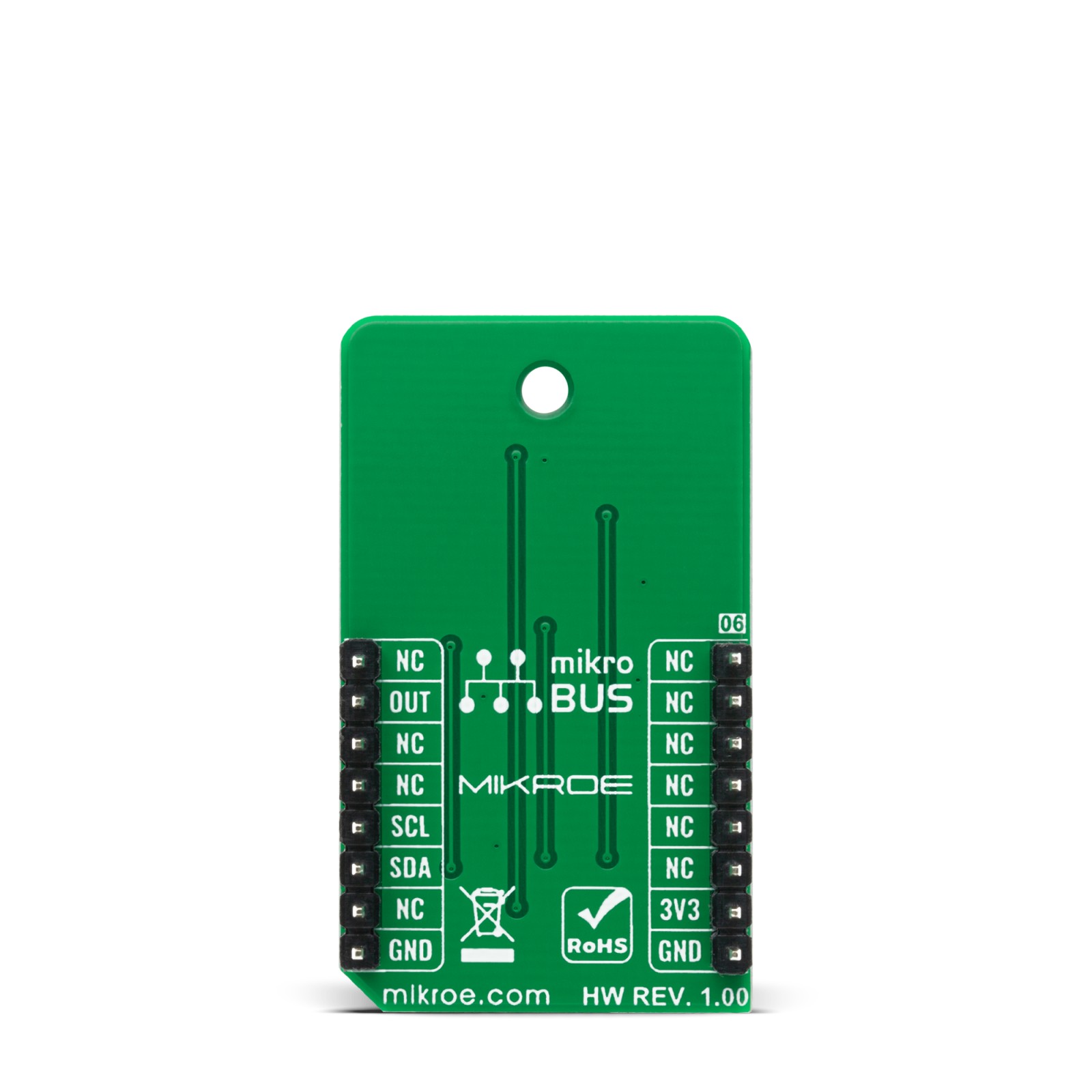
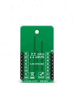
This table shows how the pinout on Air quality 7 Click corresponds to the pinout on the mikroBUS™ socket (the latter shown in the two middle columns).
Onboard settings and indicators
| Label | Name | Default | Description |
|---|---|---|---|
| LD1 | PWR | – | Power LED Indicator |
Air quality 7 Click electrical specifications
| Description | Min | Typ | Max | Unit |
|---|---|---|---|---|
| Supply Voltage | – | 3.3 | – | V |
| CO2 Monitoring Range | 400 | – | 2000 | ppm |
| VOCs Monitoring Range | 0 | – | 1000 | ppB |
| Operating Temperature Range | 0 | – | 50 | °C |
Software Support
We provide a library for the Air quality 7 Click on our LibStock page, as well as a demo application (example), developed using MikroElektronika compilers. The demo can run on all the main MikroElektronika development boards.
Library Description
This library allows user to check CO2 (Carbon Dioxide) and tVOC (Total Volatile Organic Compounds) level of the air quality. The recalibration of the device is also allowed by this library. For more details, please, check full documentation.
Key functions:
void airquality7_set_ppmco2( uint8_t *ppmco2_value );– This function is used to send the ppmCO2 value given by an external analyzer to the Air quality 7 click in order to recalibrate its outputs.airquality7_err_t airquality7_get_status( uint16_t *tvoc_ppb, uint16_t *co2_ppm, uint32_t *res_val_ohm, uint8_t *err_byte );– This function is used to read the Air quality 7 click status coded on tVOC data byte [0 – 1000 ppb], CO2 data byte [400 – 2000 ppm], resistor value data 3 bytes [Ohm], error status byte and CRC byte.airquality7_err_t airquality7_get_r0_calib( uint16_t *r0_kohm );– This function is used to read the R0 (calibration) value in [kOhms] coded on 2 data bytes and CRC byte.
Examples description
The application is composed of three sections :
- System Initialization – Initializes all necessary peripherals and pins. Performs a delay time of a couple seconds because the Air quality 7 Click needs some time to establish the measurements.
- Application Initialization – Initializes I2C driver and reads revision of the module. If CRC check is OK allows the program to go on, and if it’s not OK, needs to restart the program.
- Application Task – Reads air quality status every 1500ms and shows the results on serial terminal.
void application_task( )
{
    airquality7_err_code = airquality7_get_status( &airquality7_tvoc_ppb,
                                                   &airquality7_co2_ppm,
                                                   &airquality7_res_val_ohm,
                                                   AIRQUALITY7_NULL );

    if ( airquality7_err_code == AIRQUALITY7_ERR_OK )
    {
        char log_txt[ 50 ];
        uint8_t cnt;

        log_txt[ 0 ] = 13;
        log_txt[ 1 ] = 0;
        mikrobus_logWrite( log_txt, _LOG_TEXT );

        for ( cnt = 0; cnt < 70; cnt++ )
        {
            mikrobus_logWrite( " ", _LOG_TEXT );
            Delay_ms( 5 );
        }

        mikrobus_logWrite( log_txt, _LOG_TEXT );

        WordToStr( airquality7_tvoc_ppb, log_txt );
        Ltrim( log_txt );
        mikrobus_logWrite( " tVOC [ppb] = ", _LOG_TEXT );
        mikrobus_logWrite( log_txt, _LOG_TEXT );
        mikrobus_logWrite( ";  ", _LOG_TEXT );

        WordToStr( airquality7_co2_ppm, log_txt );
        Ltrim( log_txt );
        mikrobus_logWrite( "CO2 [ppm] = ", _LOG_TEXT );
        mikrobus_logWrite( log_txt, _LOG_TEXT );
        mikrobus_logWrite( ";  ", _LOG_TEXT );

        LongWordToStr( airquality7_res_val_ohm, log_txt );
        Ltrim( log_txt );
        mikrobus_logWrite( "Resistor value [ohm] = ", _LOG_TEXT );
        mikrobus_logWrite( log_txt, _LOG_TEXT );
    }

    Delay_ms( 1500 );
}
The full application code, and ready to use projects can be found on our LibStock page.
Other mikroE Libraries used in the example:
- Conversions
- C_String
- I2C
- UART
Additional notes and informations
Depending on the development board you are using, you may need USB UART click, USB UART 2 click or RS232 click to connect to your PC, for development systems with no UART to USB interface available on the board. The terminal available in all MikroElektronika compilers, or any other terminal application of your choice, can be used to read the message.
mikroSDK
This Click board™ is supported with mikroSDK – MikroElektronika Software Development Kit. To ensure proper operation of mikroSDK compliant Click board™ demo applications, mikroSDK should be downloaded from the LibStock and installed for the compiler you are using.
For more information about mikroSDK, visit the official page.
Resources
Downloads
| Weight | 19 g |
|---|---|
| Brand | MikroElektronika |

