Air quality 3 Click
R600.00 ex. VAT
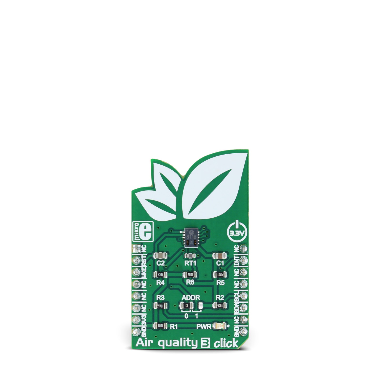
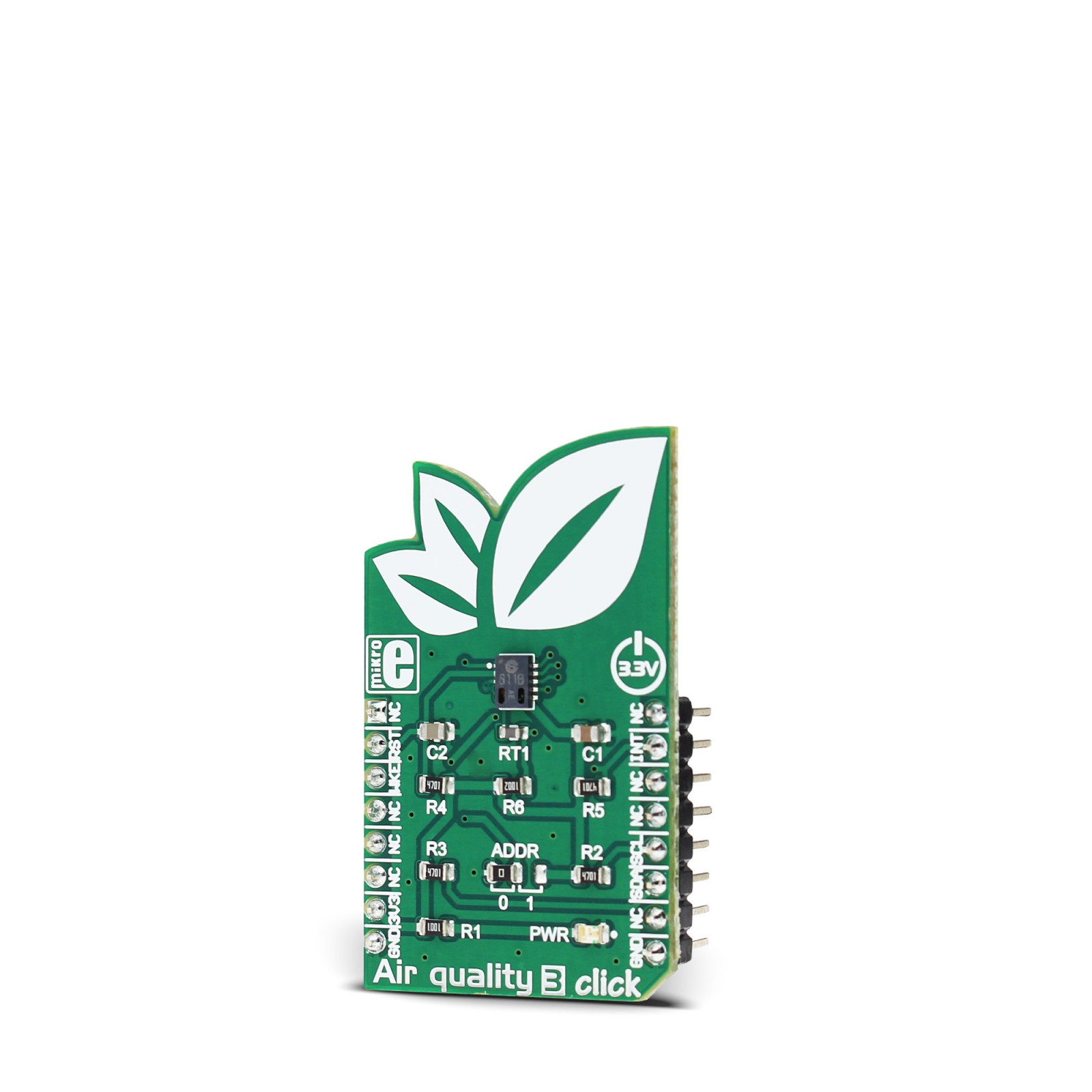
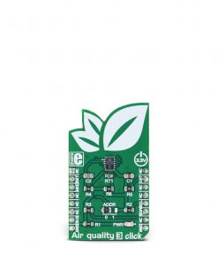
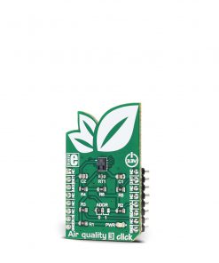
Air quality 3 click is the air quality measurement device, which is able to output both equivalent CO2 levels and total volatile organic compounds (TVOC) concentration in the indoor environment. The Click board™ is equipped with the state-of-the-art air quality sensor IC, which has an integrated MCU and a specially designed metal oxide (MOX) gas sensor microplate, allowing for high reliability, fast cycle times and a significant reduction in the power consumption, compared to other MOX sensor-based devices. The Click board™ is also equipped with a temperature compensating element, which allows for increased measurement accuracy.
Stock: Lead-time applicable.
| 5+ | R570.00 |
| 10+ | R540.00 |
| 15+ | R510.00 |
| 20+ | R490.80 |
Air quality 3 click is the air quality measurement device, which is able to output both equivalent CO2 levels and total volatile organic compounds (TVOC) concentration in the indoor environment. The Click board™ is equipped with the state-of-the-art air quality sensor IC, which has an integrated MCU and a specially designed metal oxide (MOX) gas sensor microplate, allowing for high reliability, fast cycle times and a significant reduction in the power consumption, compared to other MOX sensor-based devices. The Click board™ is also equipped with a temperature compensating element, which allows for increased measurement accuracy.
This Click board™ outputs processed values for the equivalent CO2 levels (parts per million – ppm) and TVOC (parts per billion – ppb), based on raw gas readings, processed by the internal MCU. The values can be directly accessed via the I2C bus, which saves the software development time, allowing faster time to market. These features make Air quality 3 click a perfect solution for a wide range of both portable and stationary applications for measuring and monitoring the air quality in offices, storage areas, for home and building air conditioning automation and similar applications that require a reliable, low power eCO2 and TVOC level measurements.
How does it work?
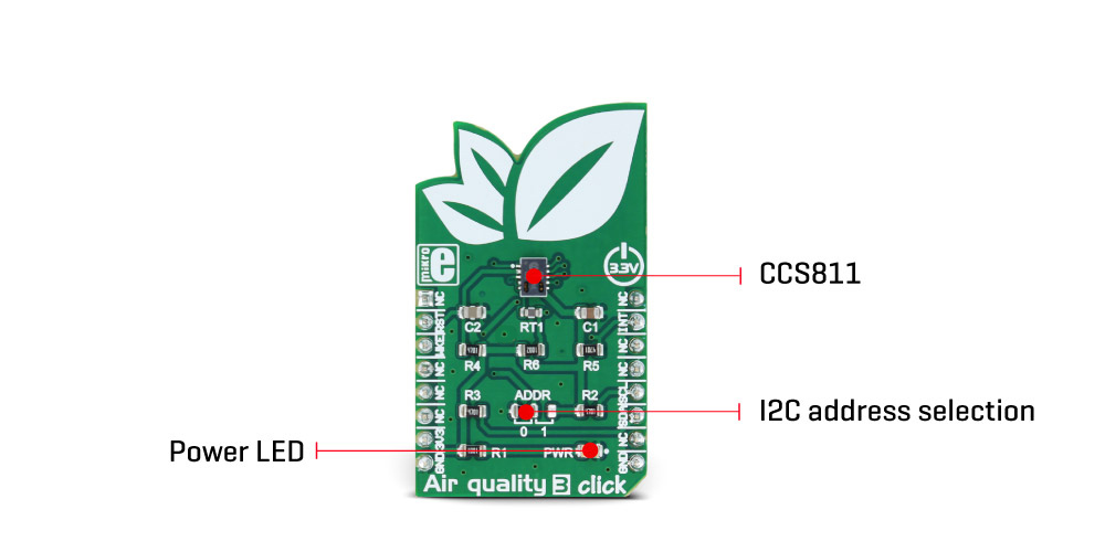
Air quality 3 click is equipped with the CCS811, an advanced ultra-low power digital gas sensor for monitoring the indoor air quality (IAQ), from ams. This IC consists of an analog section consisting of a MOX gas sensor, based on ams unique micro-hotplate technology which allows high reliability, fast cycle times and very low power consumption; and the digital section, which consists of an embedded microcontroller (MCU) and an analog to digital converter (ADC). The CCS811 sensor IC employs advanced algorithms to calculate the raw sensor data and output the equivalent CO2 and TVOC values. It utilizes the internal MCU for this purpose, reducing the payload on the host MCU.
Because of the nature of the MOX sensors, the CCS811 sensitivity will change over the time, especially in early life use. The internal sensor resistance will change the most for the first 48 hours of operation. So, to achieve a proper operation of this sensor, it has to be calibrated during several different phases of its lifecycle. Since this step is important for achieving accurate IAQ results, it is strongly advised to be carefully studied from the CCS811 datasheet.
There are five operating modes available for the Air quality 3 click:
- Mode 0 (idle mode), which uses the least power of all modes. The sensor stays dormant and no readings are made in this mode
- Mode 1 (constant power mode) the IAQ measurement is performed every second
- Mode 2 (pulse heating mode) the IAQ measurement is performed every 10 seconds
- Mode 3 (low power pulse heating mode) the IAQ measurement is performed every 60 seconds
- Mode 4 (constant power mode) the IAQ measurement is performed every 250ms
These modes affect the power consumption of the Air Quality 3 click, as well as the frequency of the data sampling. Depending on the given conditions, the device can be set to be operated in any of these modes. However, it should be noted that the device should be set to idle mode for at least 10 minutes, before switching from higher frequency measurement mode, to a lower frequency measurement mode. The TVOC and eCO2 values are calculated for modes 1, 2 and 3, while Mode 4 is intended to be used when external data processing is required, giving only raw value readings.
The Click board™ communicates with the host MCU via the I2C bus. SCL and SDA pins of the CCS811 IC are routed to the corresponding mikroBUS™ pins, allowing easy and secure connection with the development system. There is yet another pin used with the I2C communication, that is not the part of the standard I2C bus: the #WAKE pin has to be set to a LOW logic level before the communication is attempted. This pin is routed to the CS pin of the mikroBUS™. The I2C bus lines are equipped with the pull-up resistors, so a communication can be established as soon as the click board is installed on the mikroBUS™.
The least significant bit of the I2C address is routed to the external pin of the CCS811 IC and it can be set to either HIGH or a LOW logic level. This can be done by an onboard SMD jumper, labeled as ADDR. It is useful when more than one device is used on the same I2C bus.
The #RESET pin is used to reset the device and it has to be pulled to a LOW logic level for at least 20μs. It is pulled to a HIGH logic level by the onboard resistor and filtered by a capacitor, to prevent random reset of the device. The #RESET of the CCS811 sensor IC is routed to the mikroBUS RST pin.
The #INT pin allows another powerful feature of the Air Quality 3 click to be used – a programmable interrupt request. This pin can be driven to a LOW state when there is data ready to be read via the I2C. It can also be programmed to be driven when the eCO2 measurement data exceeds the programmed threshold by the hysteresis value. This can be extremely useful for making an early CO2 warning system. Interrupts, in general, are very useful to avoid constant polling by the MCU, saving resources and energy that way. The #INT of the CCS811 sensor IC is routed to the mikroBUS INT pin.
Provided Click board ™ library contains functions which can be used to read and configure the Air quality 3 click in a simple and comprehensive way. The provided example application demonstrates how to use these functions properly and can be used for a future development.
Specifications
Type
Air Quality ,Gas
Applications
A perfect solution for various air conditioning systems, ventilation systems and other IoT applications where accurate, detailed and reliable air quality readings are required.
On-board modules
CCS811, an advanced ultra-low power digital gas sensor for monitoring the indoor air quality (IAQ), from ams.
Key Features
Onboard MCU processing, programmable interrupts, advanced MOX gas sensor technology, direct I2C reading of calculated values which allow fast time to market and rapid development
Interface
I2C
Compatibility
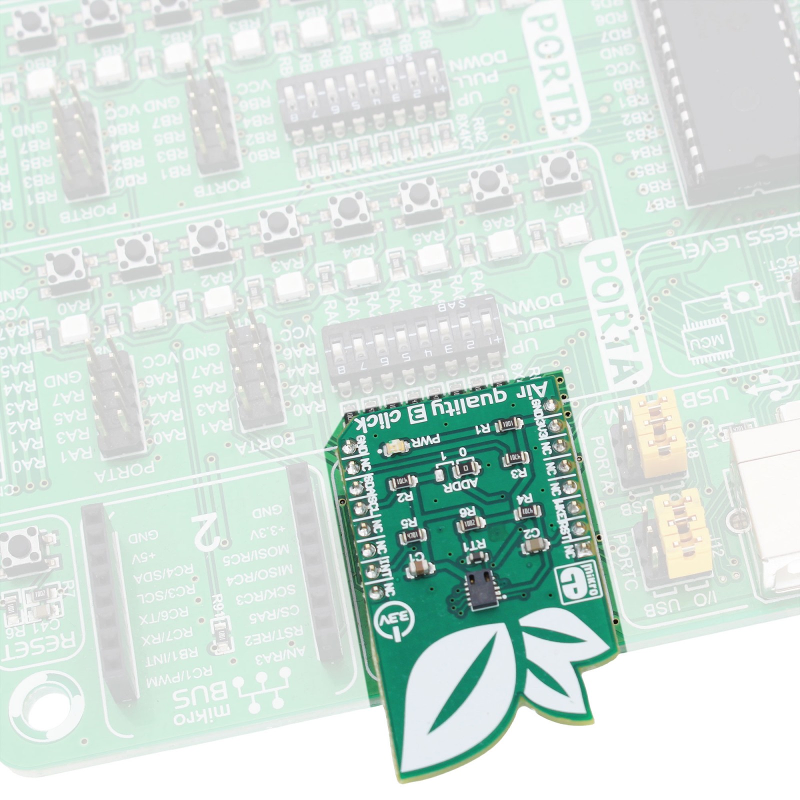
mikroBUS
Click board size
M (42.9 x 25.4 mm)
Input Voltage
3.3V
Pinout diagram
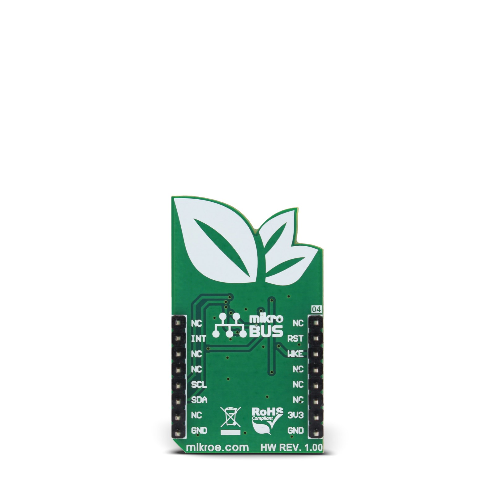
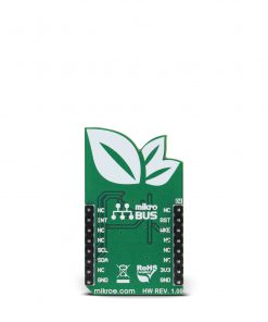
This table shows how the pinout on Air quality 3 click corresponds to the pinout on the mikroBUS™ socket (the latter shown in the two middle columns).
Onboard settings and indicators
| Label | Name | Default | Description |
|---|---|---|---|
| LD1 | PWR | – | Power LED indicator |
| JP1 | ADDR | Left | Jumper for CCS811 I2C address selection |
Software support
We provide a library for Air quality 3 click on our LibStock page, as well as a demo application (example), developed using MikroElektronika compilers. The demo application can run on all the main MikroElektronika development boards.
Library Description
The library carries all necessary functions to have complete control over Air quality 3 click.
Key functions
void airq3_getCO2andTVOC( uint16_t *algData ) - Read Co2 and TVOC values.
void airq3_setMeasurementMode( uint8_t mode ) - Set measurement mode.
void airq3_init() - Default module initialization must be called before module usage.
Examples Description
The demo application is composed of three sections:
- System Initialization – Initializes I2C module, set CS and RST pin as OUTPUT and INT pin as INPUT.
- Application Initialization – Initializes Driver, and module with default settings and also setup measurement mode.
- Application Task – (code snippet) – This function read CO2 and TVOC value in the air and LOG information to UART.
The operation is repeated each one second.
void applicationTask()
{
 airq3_getCO2andTVOC(&AIRQ3_Data[0]);

 ByteToStr(AIRQ3_Data[0],text);
 mikrobus_logWrite("CO2 value : ",_LOG_TEXT);
 mikrobus_logWrite(text,_LOG_TEXT);
 mikrobus_logWrite(" ppm",_LOG_LINE);

 ByteToStr(AIRQ3_Data[1],text);
 mikrobus_logWrite("TVOC value : ",_LOG_TEXT);
 mikrobus_logWrite(text,_LOG_TEXT);
 mikrobus_logWrite(" ppb",_LOG_LINE);

 Delay_1sec();
}
The full application code, and ready to use projects can be found on our LibStock page.
mikroE Libraries used in the example:
- UART
- I2C
Additional notes and information
Depending on the development board you are using, you may need USB UART click, USB UART 2 click or RS232 click to connect to your PC, for development systems with no UART to USB interface available on the board. The terminal available in all MikroElektronika compilers, or any other terminal application of your choice, can be used to read the message.
mikroSDK
This click board is supported with mikroSDK - MikroElektronika Software Development Kit. To ensure proper operation of mikroSDK compliant click board demo applications, mikroSDK should be downloaded from the LibStock and installed for the compiler you are using.
For more information about mikroSDK, visit the official page.
Resources
Downloads
| Weight | 18 g |
|---|---|
| Brand | MikroElektronika |
