How does it work?
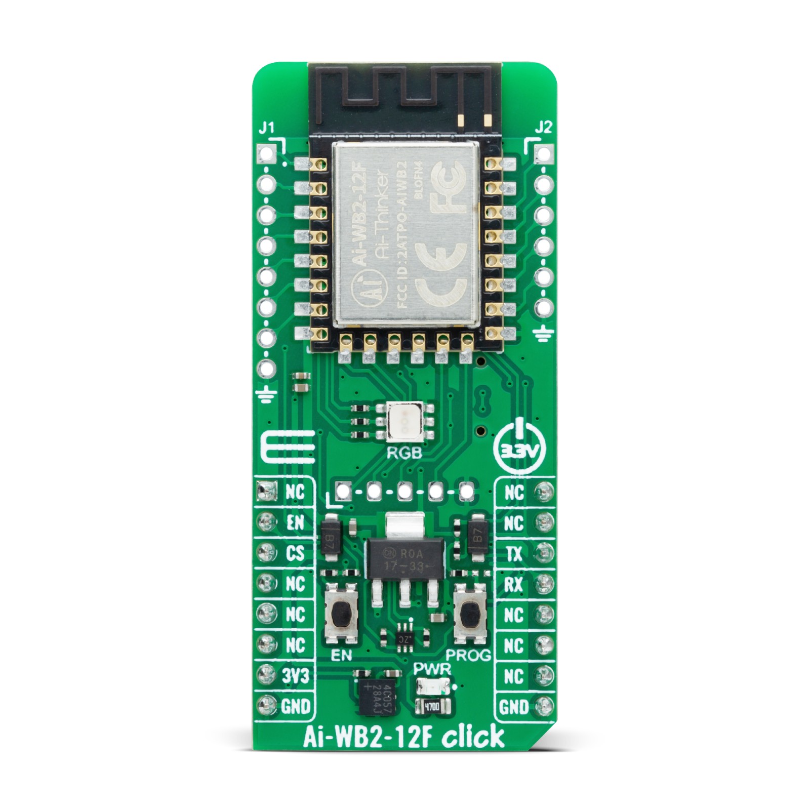
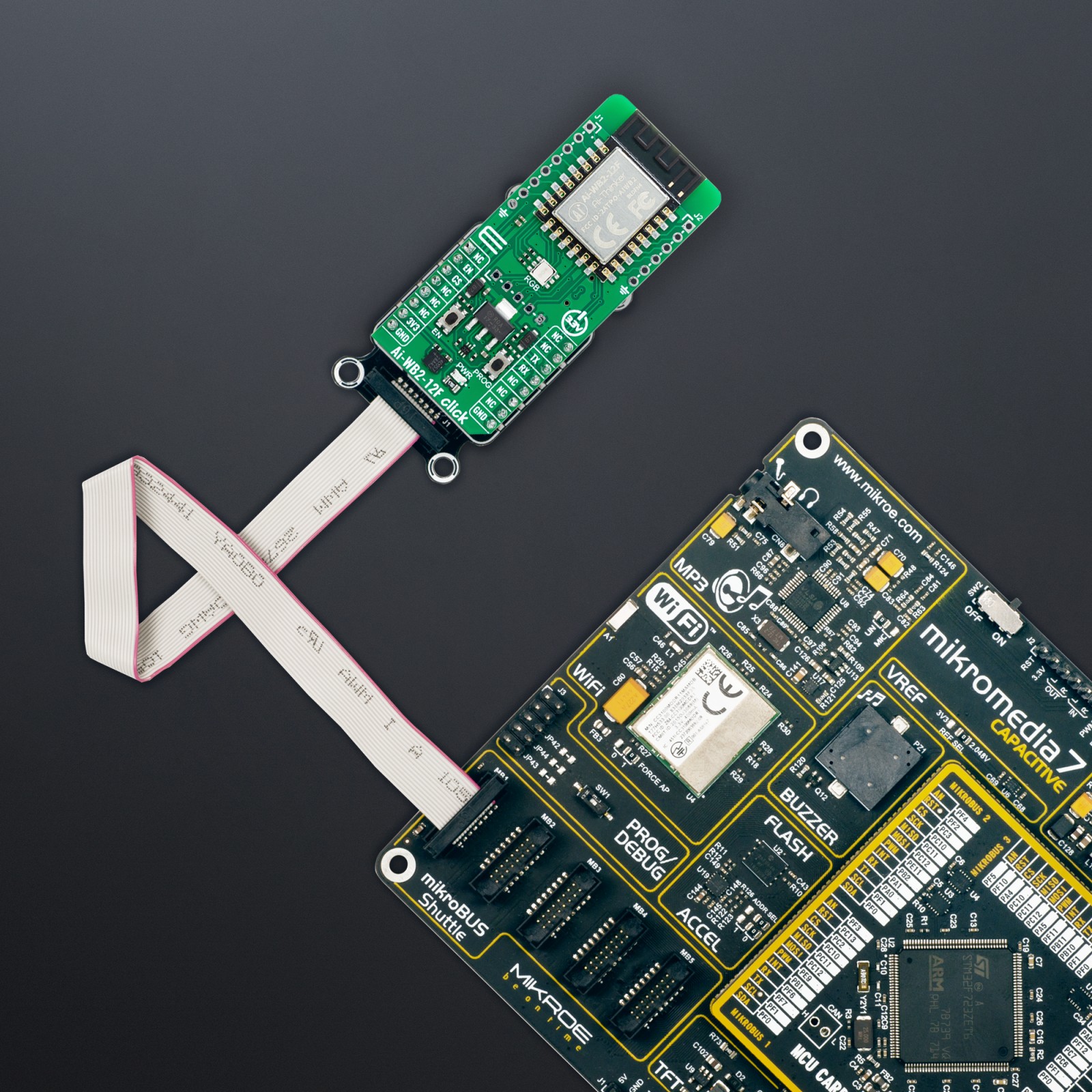
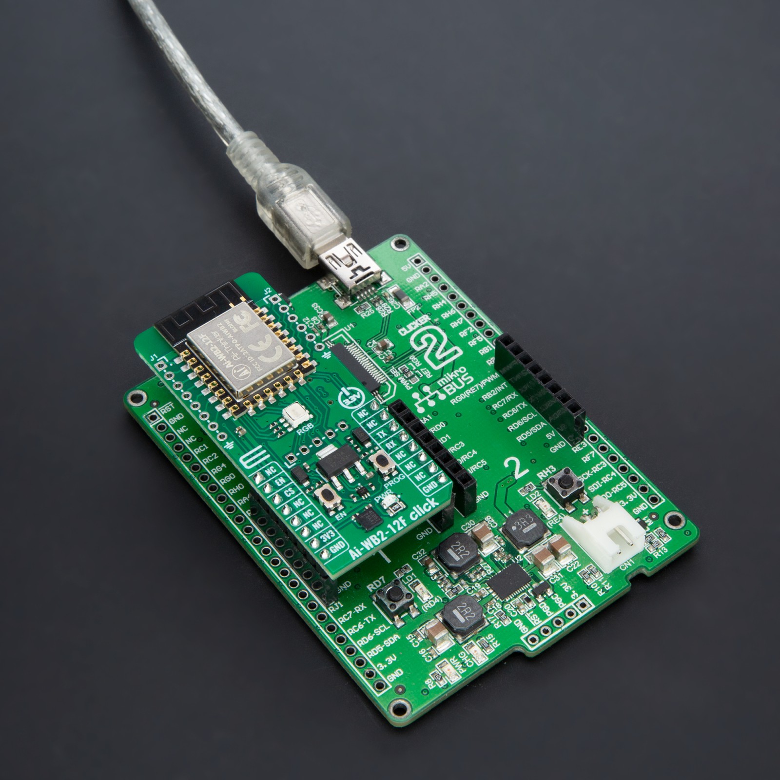
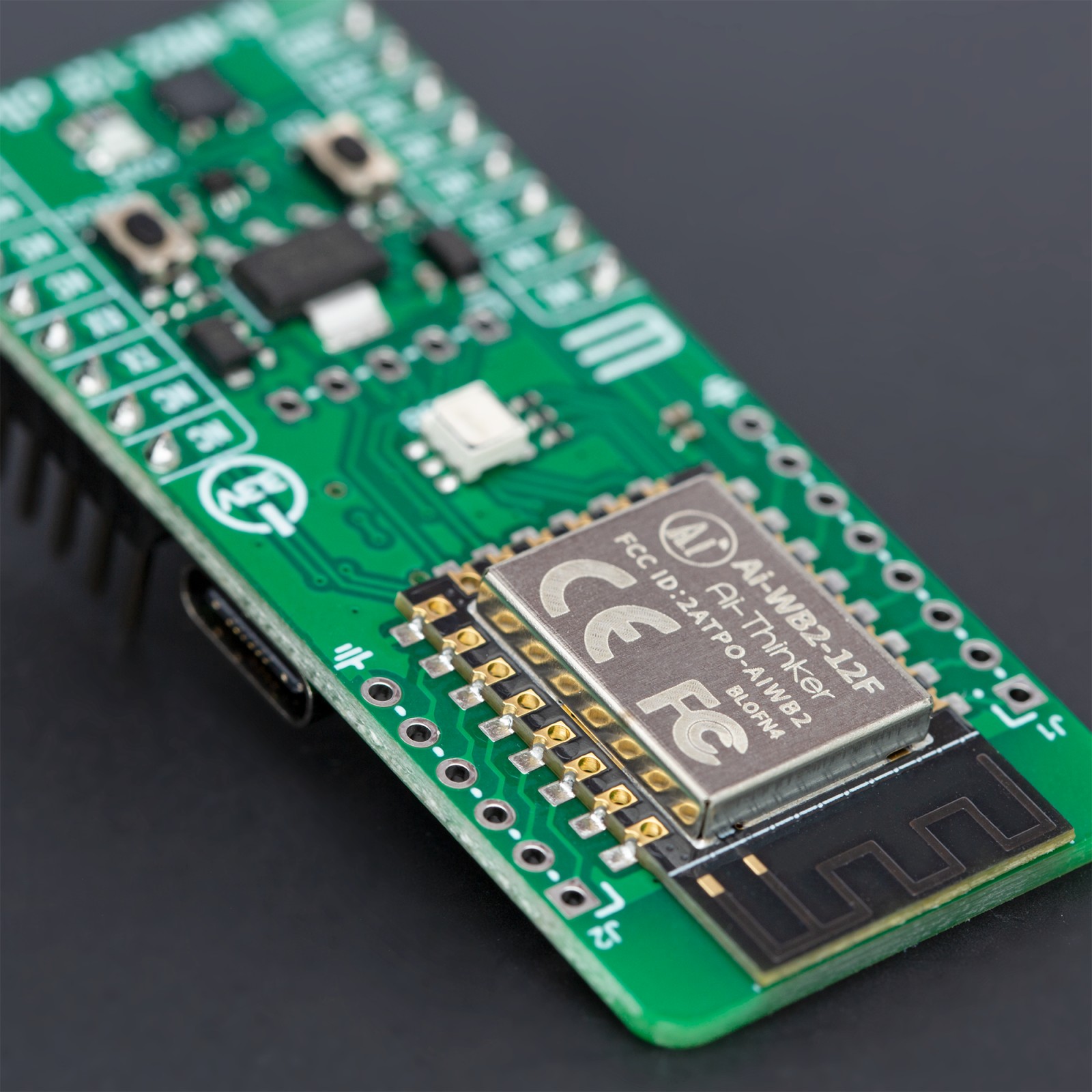
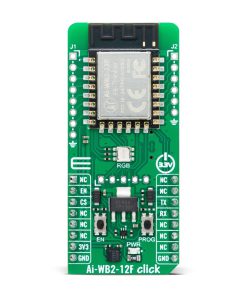
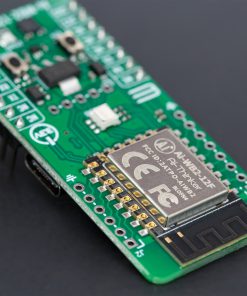
Ai-WB2-12F Click is based on the Ai-WB2-12F, a WiFi and BLE module from Ai-Thinker Technology. At its center lies the BL602 chip, which serves as the primary processor. This chip equips the module with support for WiFi 802.11b/g/n and BLE 5.0 protocols, featuring a low-power 32-bit RISC CPU, 276KB of RAM, and a comprehensive range of peripheral interfaces such as SDIO, SPI, UART, I2C, IR Remote, PWM, ADC, DAC, PIR, and GPIO, among others. Its design is made for extensive application in the Internet of Things (IoT), wearable technology, smart home solutions, and more.
In terms of additional specifications, the module boasts an inbuilt PCB antenna covering a frequency range from 2400 to 2483.5MHz, alongside extensive WiFi security protocols, including WPS, WEP, WPA, WPA2 Personal, WPA2 Enterprise, and WPA3. It also supports BLE 5.0 and Bluetooth Mesh, various operational modes such as Station + BLE and Station + SoftAP + BLE, secure boot with ECC-256 signature mirroring, an AES encryption engine for 128/192/256-bit keys, a true random number generator, and a public key accelerator for extensive cryptographic operations. The module facilitates a variety of sleep modes, boasting a deep sleep current of just 12μA, and allows for easy setup with universal AT commands.
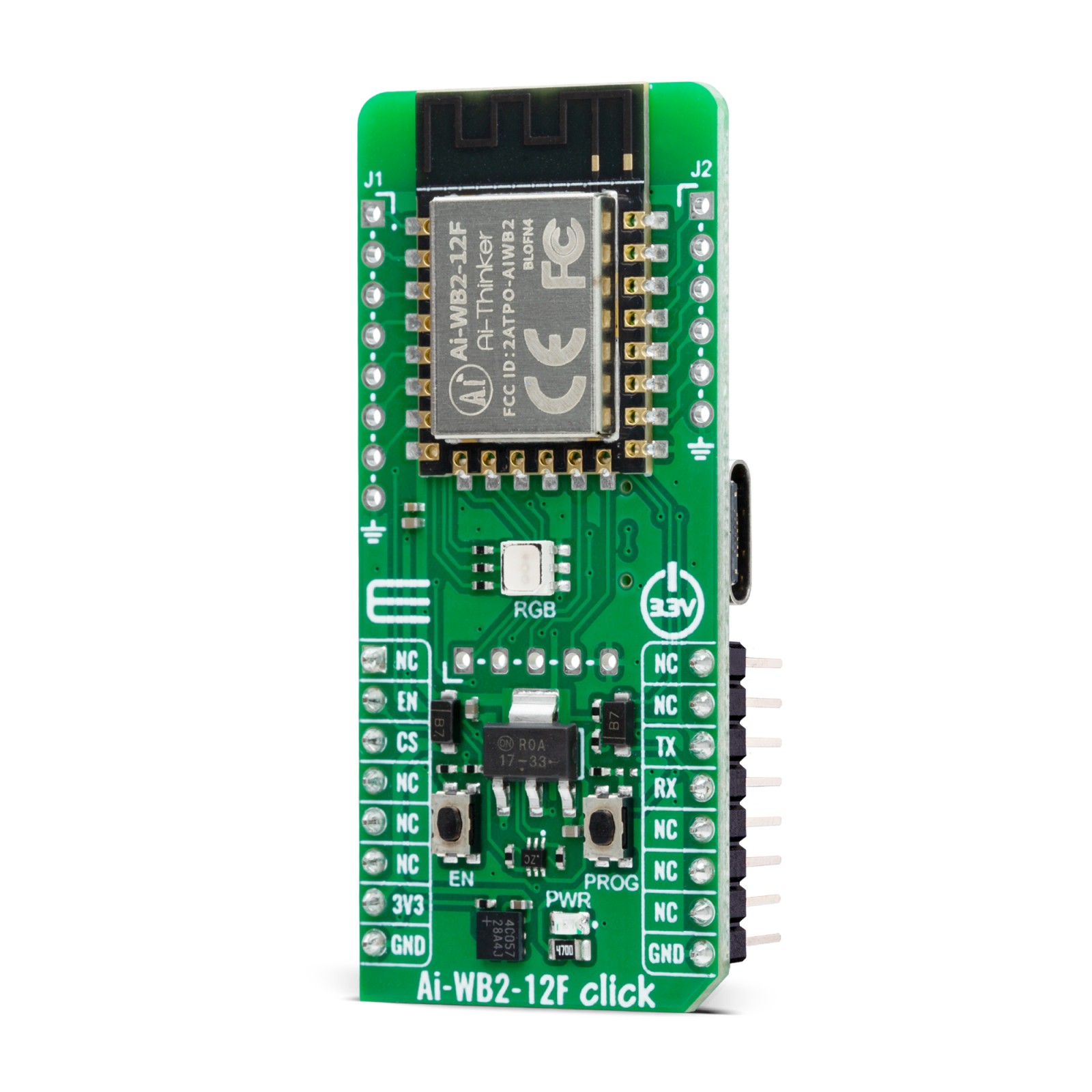
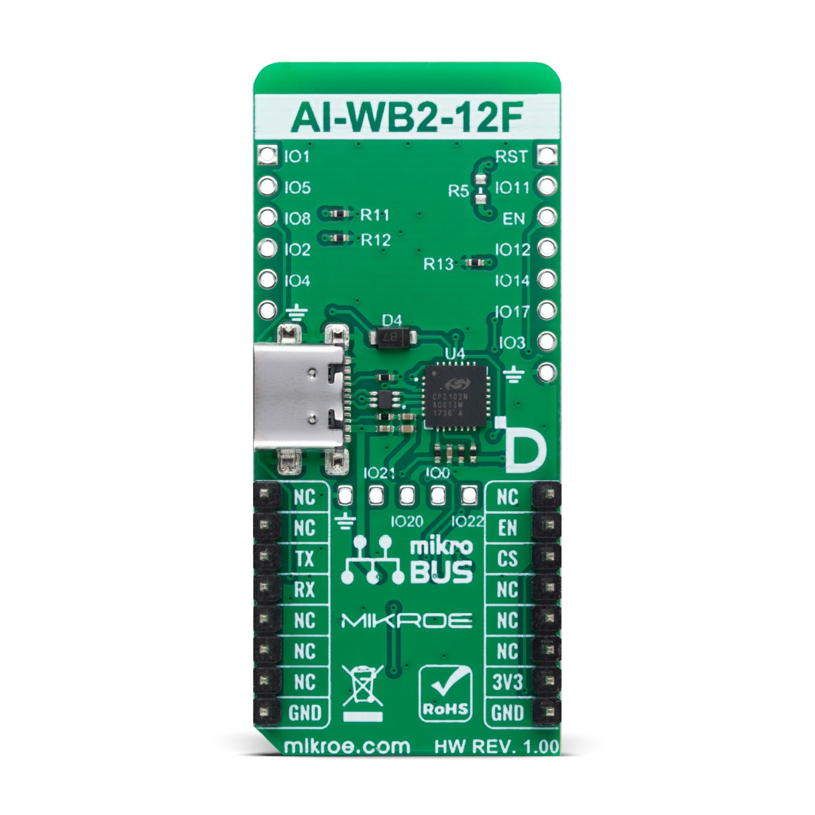
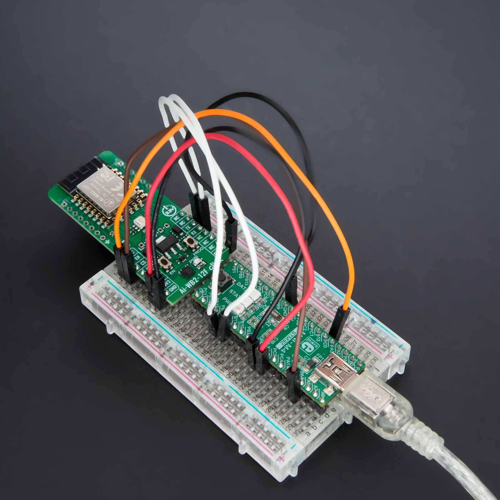
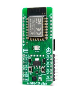
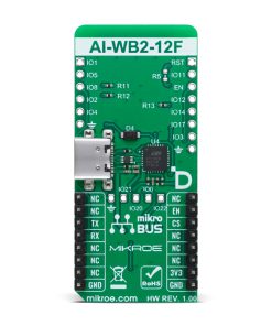
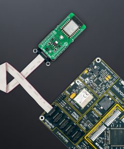
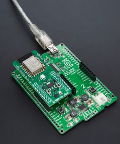
Moving on to the board’s connectivity features, this Click board™ employs a UART interface for communication with the host MCU, using standard UART RX and TX pins to exchange AT commands. By default, it communicates at a baud rate of 115200bps. The Click board™ is additionally equipped with a USB type C connector, enabling direct power supply and configuration via a PC.
The board also incorporates a reset feature through the R5 resistor (disabled by default with unpopulated R5 resistor) connected to the EN pin of the mikroBUS™ socket, an EN button for module enabling, and a PROG button dedicated to firmware programming. An RGB diode serves as a status indicator, signaling the active I/O pin—red for IO14, green for IO17, and blue for IO3. Depending on the user’s requirements, these pins are adaptable for various uses such as SPI, PWM, or ADC. The user-configurable I/O pins are not available by default. If you need to use it, please contact Ai-Thinker.
This Click board™ can be operated only with a 3.3V logic voltage level. The board must perform appropriate logic voltage level conversion before using MCUs with different logic levels. Also, it comes equipped with a library containing functions and an example code that can be used as a reference for further development.
Specifications
Type
WiFi+BLE
Applications
Ideal for developers who need WiFi and BLE for their projects, providing a simple and secure platform for creating IoT, wearable, and smart home devices
On-board modules
Ai-WB2-12F – WiFi and BLE module from Ai-Thinker Technology
Key Features
Supporting WiFi 802.11b/g/n and BLE 5.0 protocols, low-power 32-bit RISC CPU, many peripheral interfaces, onboard PCB antenna, WiFi security protocols, BLE 5.0 and Bluetooth Mesh, encryption and security, and more
Interface
UART,USB
Feature
ClickID
Compatibility
mikroBUS™
Click board size
L (57.15 x 25.4 mm)
Input Voltage
3.3V
Pinout diagram
This table shows how the pinout on Ai-WB2-12F Click corresponds to the pinout on the mikroBUS™ socket (the latter shown in the two middle columns).
Onboard settings and indicators
Label | Name | Default | Description |
---|---|---|---|
LD1 | PWR | – | Power LED Indicator |
LD2 | RGB | – | Module Status LED Indicator |
T1 | PROG | – | FW Programming Button |
T2 | EN | – | Module Enable Button |
Ai-WB2-12F Click electrical specifications
Description | Min | Typ | Max | Unit |
---|---|---|---|---|
Supply Voltage | – | 3.3 | – | V |
Frequency Range | 2400 | – | 2483.5 | MHz |
WiFi Output Power | – | 19 | – | dBm |
BLE Output Power | – | 9 | 15 | dBm |
WiFi Sensitivity | – | -98 | – | dBm |
BLE Sensitivity | – | -96 | – | dBm |
Software Support
We provide a library for the Ai-WB2-12F Click as well as a demo application (example), developed using MIKROE compilers. The demo can run on all the main MIKROE development boards.
Package can be downloaded/installed directly from NECTO Studio Package Manager (recommended), downloaded from our LibStock™ or found on Mikroe github account.
Library Description
This library contains API for Ai-WB2-12F Click driver.
Key functions
-
aiwb212f_send_cmd
Ai-WB2-12F send command function. -
aiwb212f_send_cmd_with_par
Ai-WB2-12F send command with parameter function. -
aiwb212f_send_cmd_check
Ai-WB2-12F send command check function.
Example Description
This example demonstrates the use of Ai-WB2-12F Click board™ by processing the incoming data and displaying them on the USB UART.
void application_task ( void )
{
aiwb212f_example( );
}
The full application code, and ready to use projects can be installed directly from NECTO Studio Package Manager(recommended), downloaded from our LibStock™ or found on Mikroe github account.
Other Mikroe Libraries used in the example:
- MikroSDK.Board
- MikroSDK.Log
- Click.AiWB212F
Additional notes and informations
Depending on the development board you are using, you may need USB UART click, USB UART 2 Click or RS232 Click to connect to your PC, for development systems with no UART to USB interface available on the board. UART terminal is available in all MIKROE compilers.
mikroSDK
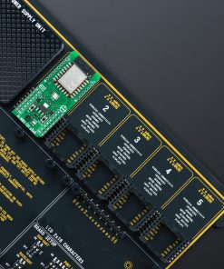
This Click board™ is supported with mikroSDK – MIKROE Software Development Kit. To ensure proper operation of mikroSDK compliant Click board™ demo applications, mikroSDK should be downloaded from the LibStock and installed for the compiler you are using.
For more information about mikroSDK, visit the official page.