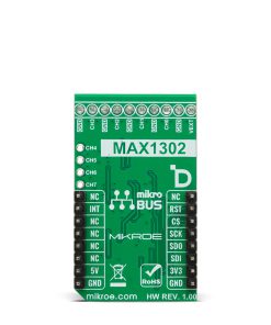
ADC 27 Click
R1,400.00 ex. VAT
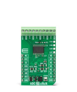
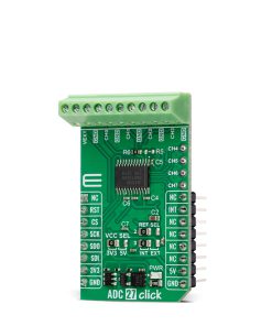
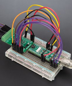
ADC 27 Click is a compact add-on board for analog signal conversion in embedded applications. This board is based on the MAX1302, a 16-bit successive-approximation ADC from Analog Devices, known for its multirange input support and low power consumption. The MAX1302 offers eight single-ended or four differential input channels, each independently configurable for various voltage ranges, and supports conversion rates up to 115ksps. ADC 27 Click also includes an internal 4.096V reference but also allows external reference input, alongside the SPI interface for communication. It is ideal for use in industrial monitoring, control systems, avionics, robotics, and data acquisition applications.
ADC 27 Click is fully compatible with the mikroBUS™ socket and can be used on any host system supporting the mikroBUS™ standard. It comes with the mikroSDK open-source libraries, offering unparalleled flexibility for evaluation and customization. What sets this Click board™ apart is the groundbreaking ClickID feature, enabling your host system to automatically detect and identify this add-on board.
Stock: Lead-time applicable.
| 5+ | R1,330.00 |
| 10+ | R1,260.00 |
| 15+ | R1,190.00 |
| 20+ | R1,145.20 |
How does it work?
ADC 27 Click is based on the MAX1302, a multirange 16-bit successive-approximation ADC from Analog Devices that supports throughput rates of up to 115ksps and offers remarkable flexibility in analog signal sampling. It communicates with the host MCU via a high-speed SPI-compatible interface, ensuring integration into a wide range of embedded applications. The MAX1302 provides eight single-ended or four true differential analog input channels, each of which can be independently configured in software for various input voltage ranges.
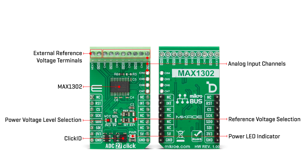
Specifically, the single-ended mode supports seven programmable ranges, including 0V to +VREF/2, -VREF/2 to 0V, 0V to +VREF, -VREF to 0V, ±VREF/4, ±VREF/2, and ±VREF, while the differential mode supports three programmable ranges: ±VREF/2, ±VREF, and ±2×VREF. This enables highly adaptable signal conditioning depending on the application’s accuracy and range requirements. The MAX1302 includes an internal precision +4.096V reference voltage, simplifying design. Yet it also allows the use of an external reference voltage between 3.800V and 4.136V for enhanced flexibility, which can be selected by setting the onboard REF SEL jumper to either INT for internal or EXT for external reference.
Designed for demanding analog measurement tasks, ADC 27 Click is well-suited for use in industrial monitoring, control systems, data acquisition setups, avionics instrumentation, and robotics, providing robust performance in environments where accuracy and configurability are essential. In addition to the standard SPI communication pins (SDO, SDI, SCK, and CS), ADC 27 Click also uses an INT pin, which serves as a data-ready indicator. This interrupt pin becomes active when a new conversion result is available, signaling the host MCU that data is ready to be read.
This Click board™ can operate with either 3.3V or 5V logic voltage levels selected via the VCC SEL jumper. This way, both 3.3V and 5V capable MCUs can use the communication lines properly. Also, this Click board™ comes equipped with a library containing easy-to-use functions and an example code that can be used as a reference for further development.
Specifications
Type
ADC
Applications
Ideal for use in industrial monitoring, control systems, avionics, robotics, and data acquisition applications
On-board modules
MAX1302 – 16-bit successive-approximation ADC from Analog Devices
Key Features
Support for eight single-ended or four differential analog input channels, programmable input voltage ranges, internal precision 4.096V reference, external reference input support from 3.800V to 4.136V, SPI-compatible communication interface, data-ready interrupt pin (INT), and more
Interface
QSPI,SPI
Feature
ClickID
Compatibility
mikroBUS™
Click board size
M (42.9 x 25.4 mm)
Input Voltage
3.3V or 5V,External
Pinout diagram
This table shows how the pinout on ADC 27 Click corresponds to the pinout on the mikroBUS™ socket (the latter shown in the two middle columns).
| Notes | Pin | Pin | Notes | ||||
|---|---|---|---|---|---|---|---|
| NC | 1 | AN | PWM | 16 | NC | ||
| ID SEL | RST | 2 | RST | INT | 15 | INT | Data-Ready Interrupt |
| SPI Select / ID COMM | CS | 3 | CS | RX | 14 | NC | |
| SPI Clock | SCK | 4 | SCK | TX | 13 | NC | |
| SPI Data OUT | SDO | 5 | MISO | SCL | 12 | NC | |
| SPI Data IN | SDI | 6 | MOSI | SDA | 11 | NC | |
| Power Supply | 3.3V | 7 | 3.3V | 5V | 10 | 5V | Power Supply |
| Ground | GND | 8 | GND | GND | 9 | GND | Ground |
Onboard settings and indicators
| Label | Name | Default | Description |
|---|---|---|---|
| LD1 | PWR | – | Power LED Indicator |
| JP1 | VCC SEL | Left | Power Voltage Level Selection 3V3/5V: Left position 3V3, Right position 5V |
| JP2-JP3 | REF SEL | Left | Reference Voltage Selection INT/EXT: Left position INT, Right position EXT |
ADC 27 Click electrical specifications
| Description | Min | Typ | Max | Unit |
|---|---|---|---|---|
| Supply Voltage | 3.3 | – | 5 | V |
| Reference Voltage | 3.8 | 4.096 | 4.136 | V |
| Resolution | – | 16 | – | bit |
| Sampling Rate | – | – | 115 | ksps |
Software Support
ADC 27 Click demo application is developed using the NECTO Studio, ensuring compatibility with mikroSDK‘s open-source libraries and tools. Designed for plug-and-play implementation and testing, the demo is fully compatible with all development, starter, and mikromedia boards featuring a mikroBUS™ socket.
Example Description
This example demonstrates the use of the ADC 27 Click board by reading voltages from multiple analog input channels configured in both single-ended and differential modes. The measured voltage values are displayed via UART.
Key Functions
adc27_cfg_setupThis function initializes Click configuration structure to initial values.adc27_initThis function initializes all necessary pins and peripherals used for this Click board.adc27_default_cfgThis function executes a default configuration of ADC 27 Click board.adc27_set_configThis function sets the configuration for the selected channel of the ADC 27 Click board.adc27_read_raw_dataThis function reads raw ADC data from the selected channel.adc27_read_voltageThis function reads the ADC value from the selected channel and converts it to a voltage level using the configured range.
Application Init
Initializes the logger and the ADC 27 Click driver, and performs the default configuration.
Application Task
Reads and logs voltage values from channels CH0-CH3 (single-ended) and CH4/CH5, CH6/CH7 (differential).
Application Output
This Click board can be interfaced and monitored in two ways:
- Application Output – Use the “Application Output” window in Debug mode for real-time data monitoring. Set it up properly by following this tutorial.
- UART Terminal – Monitor data via the UART Terminal using a USB to UART converter. For detailed instructions, check out this tutorial.
Additional Notes and Information
The complete application code and a ready-to-use project are available through the NECTO Studio Package Manager for direct installation in the NECTO Studio. The application code can also be found on the MIKROE GitHub account.
Resources
Downloads
| Weight | 20 g |
|---|---|
| Brand | MikroElektronika |