How does it work?
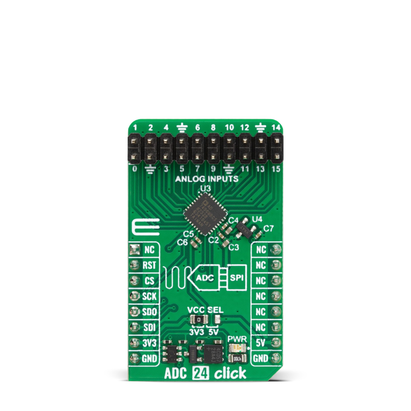
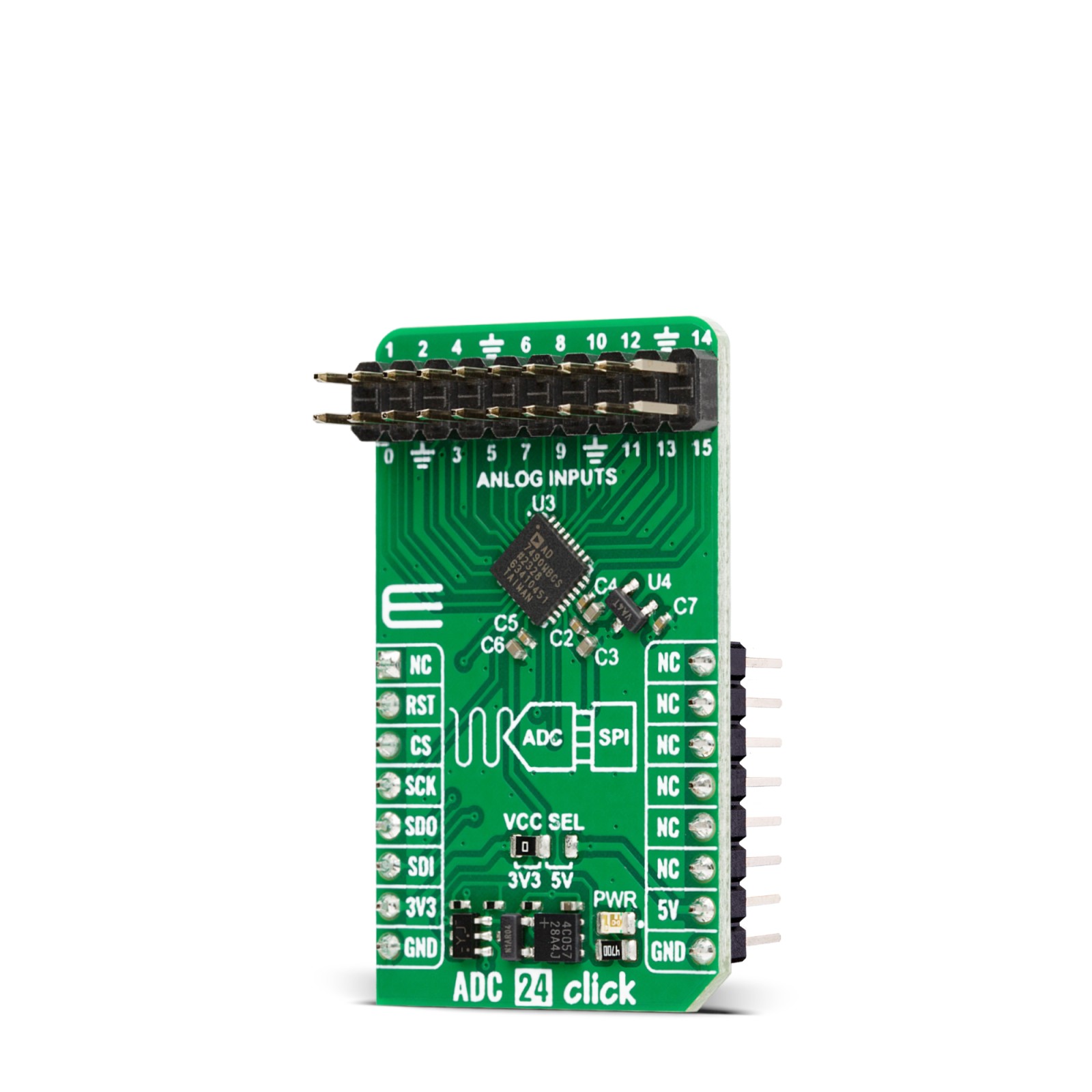
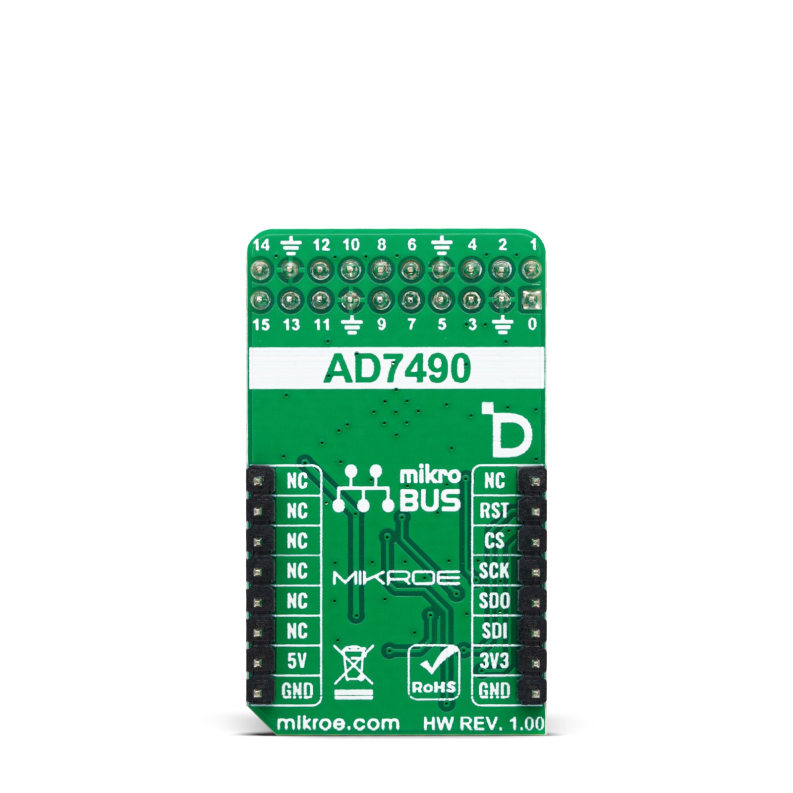
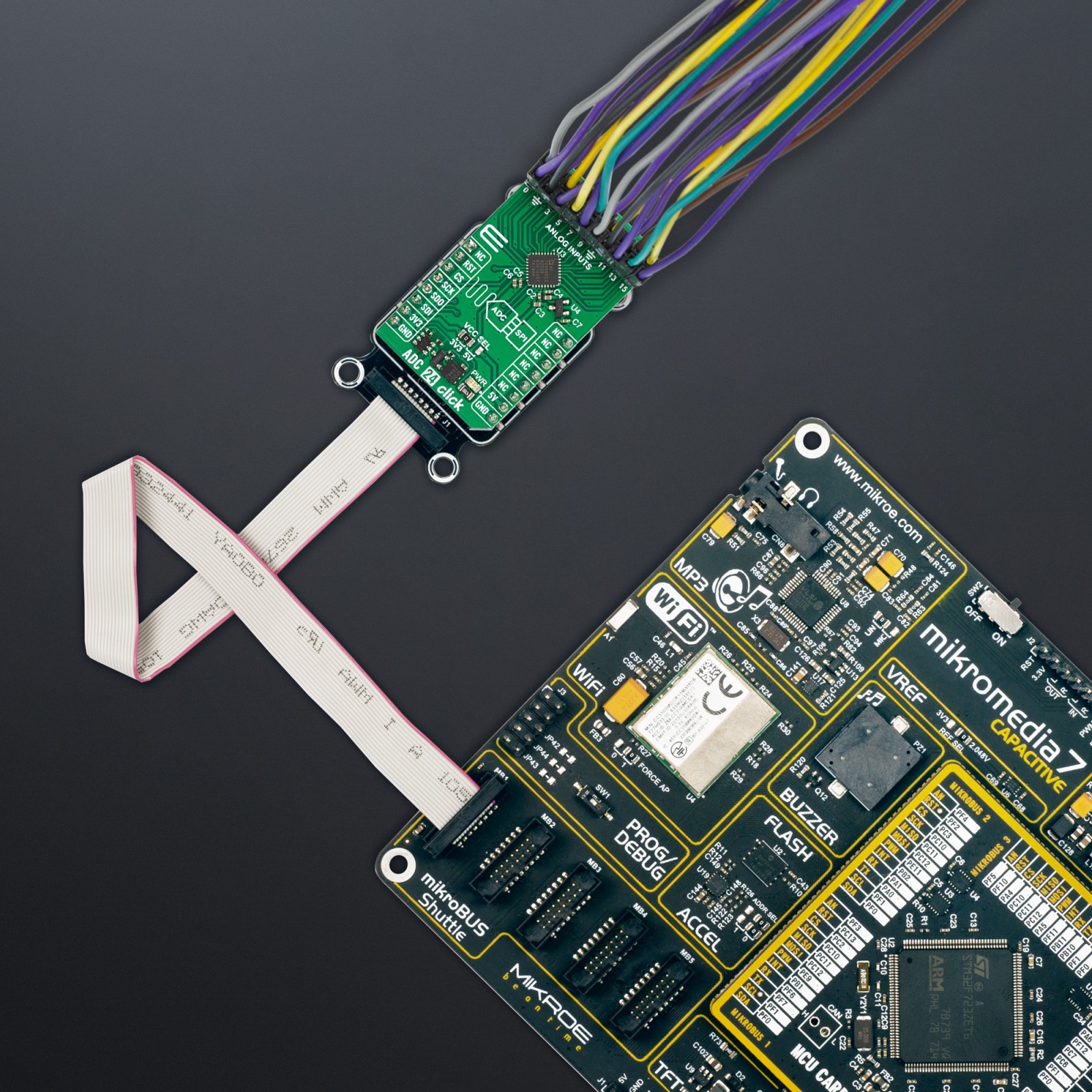
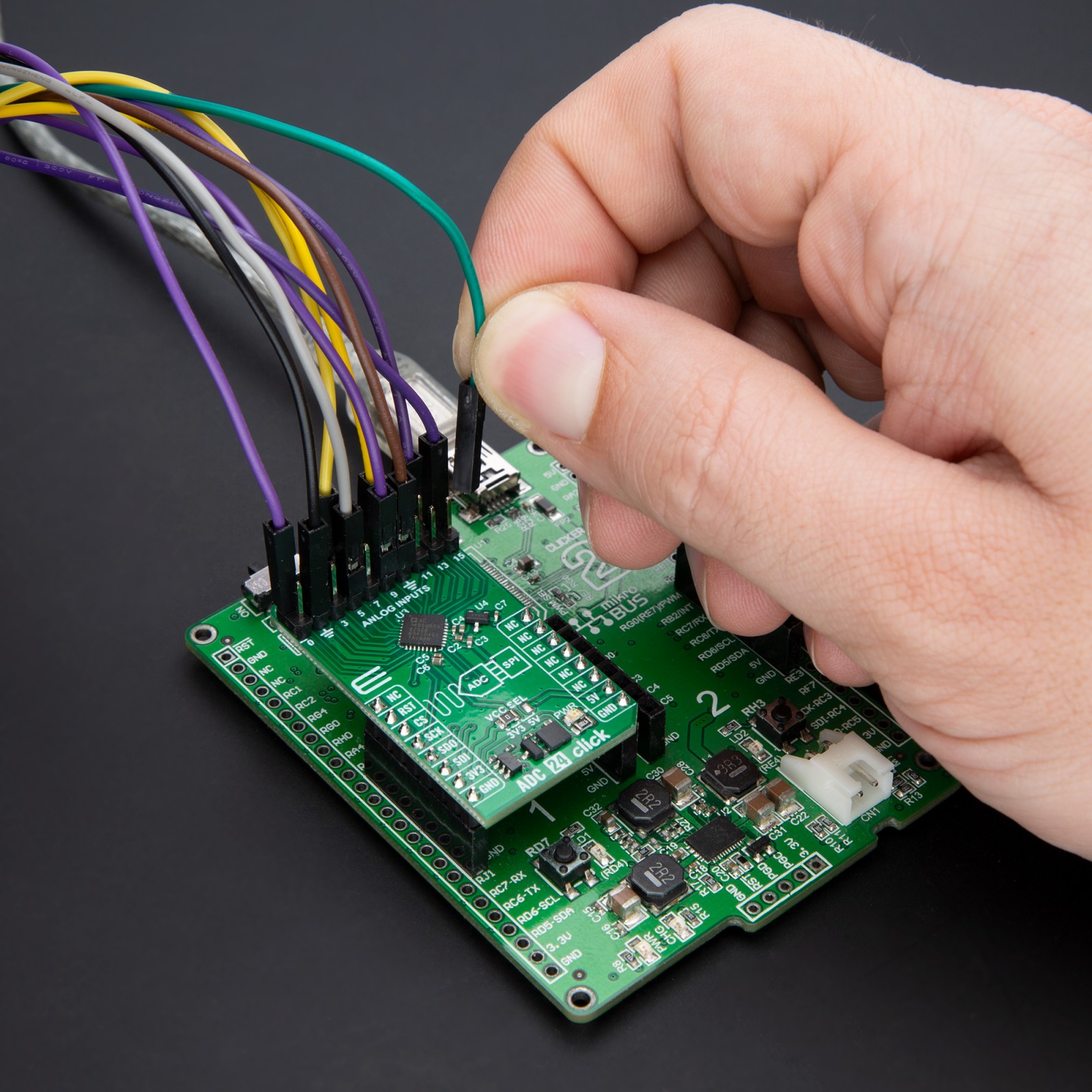
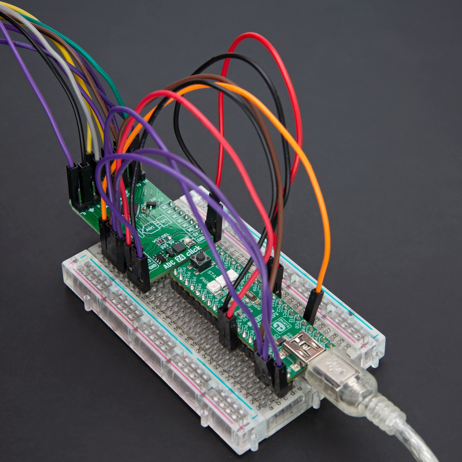
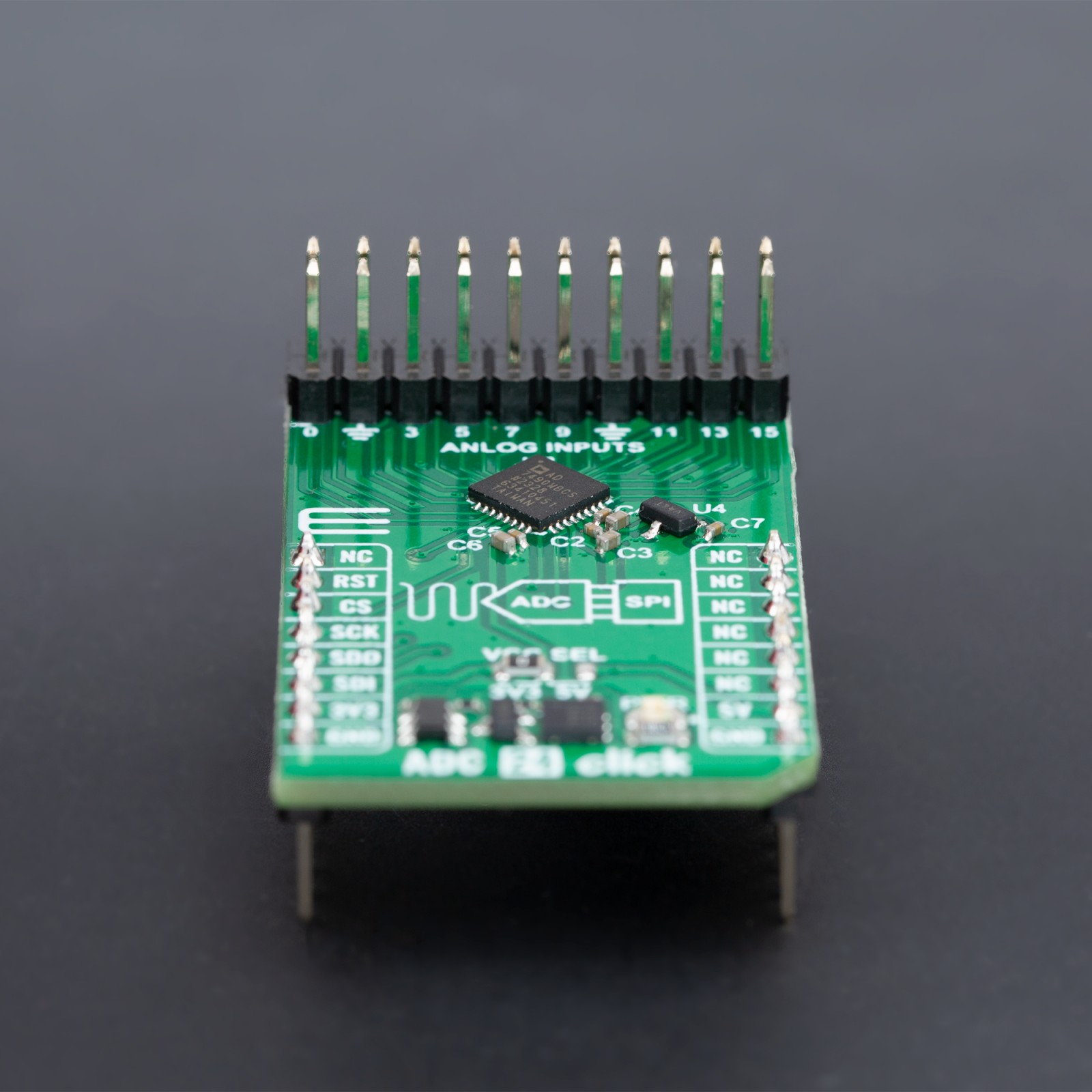
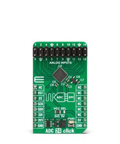
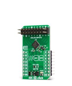
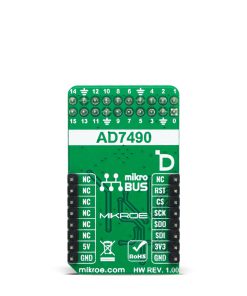
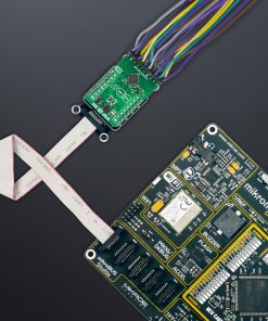
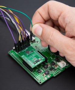
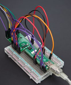
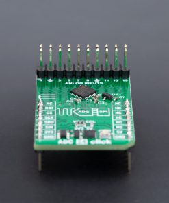
ADC 24 Click is based on the AD7490, a 12-bit, high-speed, low-power, 16-channel successive approximation ADC from Analog Devices. This ADC minimizes power consumption while maintaining high throughput rates, drawing just 2.5mA from a 5V supply at full capacity. It achieves up to 1MSPS throughput rates and incorporates a low noise, wide bandwidth track-and-hold amplifier that adeptly handles input frequencies beyond 1MHz. This Click board™ is particularly suited for applications requiring extensive system monitoring, such as multichannel system monitoring, power line monitoring, data acquisition, instrumentation, and process control.
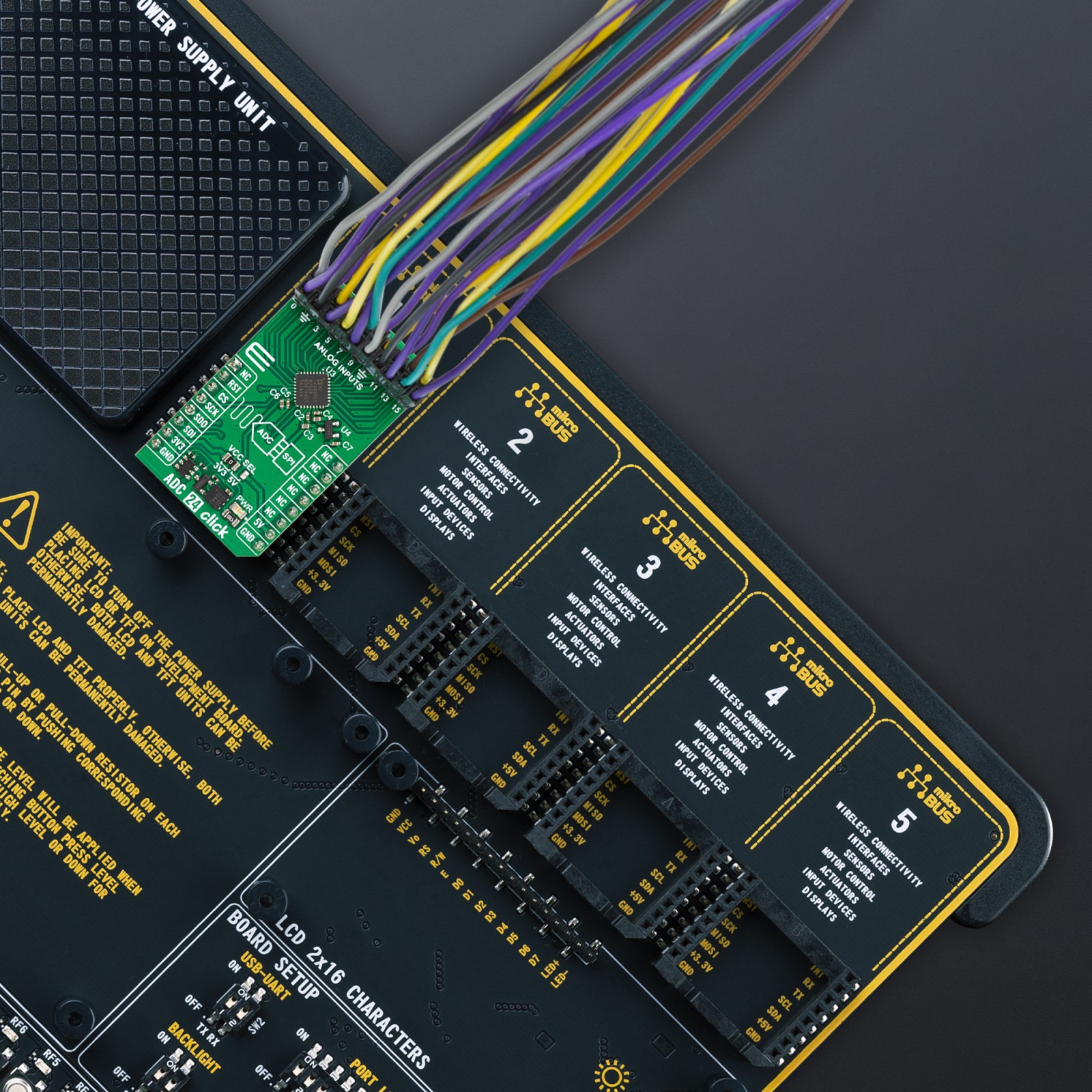
The AD7490 is equipped with 16 single-ended analog inputs, enhanced by a channel sequencer that enables the programmed and sequential conversion of channels. The analog input range is configurable, offering a 0V to REFIN or a broader 0V to 2×REFIN range, achieved by the MCP1525 voltage reference from Microchip, with fixed 2.5V output. This flexibility allows users to tailor the ADC to various measurement requirements. For accurate utilization of the 0V to 2×REFIN measurement range, powering the IC with 5V is mandatory, which is achieved with 5V from the mikroBUS™ power rail.
Moreover, the AD7490 supports multiple operational modes, such as Normal, Full Shutdown, Auto Shutdown, and Auto Standby, all of which are register-configurable. These modes provide users with various power management options to optimize the balance between power dissipation and throughput rate based on specific application needs. The conversion process and data acquisition are made using CS and the serial clock signal, ensuring straightforward interfacing with microprocessors or DSPs (SPI/QSPI™/MICROWIRE™/ DSP compatible). The input signal is sampled at the falling edge of CS, initiating conversion at this juncture without any pipeline delays.
This Click board™ can operate with either 3.3V or 5V logic voltage levels selected via the VCC SEL jumper. This way, both 3.3V and 5V capable MCUs can use the communication lines properly. Also, this Click board™ comes equipped with a library containing easy-to-use functions and an example code that can be used as a reference for further development.
Specifications
Type
ADC
Applications
Ideal for multichannel system monitoring, power line monitoring, data acquisition, instrumentation, and process control
On-board modules
AD7490 – successive approximation ADC from Analog Devices
Key Features
12-bit resolution, fast data processing, low power consumption, configurable analog input range, multiple operational modes, SPI/QSPI™/MICROWIRE™/DSP compatible, and more
Interface
SPI
Feature
ClickID
Compatibility
mikroBUS™
Click board size
M (42.9 x 25.4 mm)
Input Voltage
3.3V or 5V
Pinout diagram
This table shows how the pinout on ADC 24 Click corresponds to the pinout on the mikroBUS™ socket (the latter shown in the two middle columns).
Onboard settings and indicators
Label | Name | Default | Description |
---|---|---|---|
LD1 | PWR | – | Power LED Indicator |
JP1 | VCC SEL | Left | Logic Voltage Level Selection 3V3/5V: Left position 3V3, Right position 5V |
ADC 24 Click electrical specifications
Description | Min | Typ | Max | Unit |
---|---|---|---|---|
Supply Voltage | 3.3 | – | 5 | V |
Analog Input Range | 0 | – | 5 | V |
Resolution | 12 | – | – | bit |
Data Rate | – | – | 1 | MSPS |
Number of Channels | – | – | 16 | ch |
Software Support
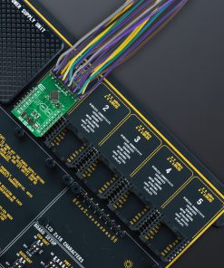
We provide a library for the ADC 24 Click as well as a demo application (example), developed using MIKROE compilers. The demo can run on all the main MIKROE development boards.
Package can be downloaded/installed directly from NECTO Studio Package Manager(recommended), downloaded from our LibStock™ or found on Mikroe github account.
Library Description
This library contains API for ADC 24 Click driver.
Key functions
-
adc24_get_voltage
This function reads the results of 12-bit ADC raw data and converts them to proportional voltage levels by using the SPI serial interface. -
adc24_get_adc_data
This function reads a conversion result and selected channel by using the SPI serial interface.
Example Description
This example demonstrates the use of the ADC 24 Click board™ by reading and writing data by using the SPI serial interface and reading results of AD conversion.
void application_task ( void )
{
uint8_t ch_pos = 0;
float voltage = 0;
for ( uint8_t n_cnt = ADC24_CH_SEL_IN_0; n_cnt <= ADC24_CH_SEL_IN_15; n_cnt++ )
{
ctrl.ch_sel = n_cnt;
if ( ADC24_OK == adc24_get_voltage( &adc24, ctrl, &ch_pos, &voltage ) )
{
log_printf( &logger, " IN%u : %.3f Vrn", ( uint16_t ) ch_pos, voltage );
}
Delay_ms( 100 );
}
log_printf( &logger, "_____________rn" );
Delay_ms( 1000 );
}
The full application code, and ready to use projects can be installed directly from NECTO Studio Package Manager(recommended), downloaded from our LibStock™ or found on Mikroe github account.
Other Mikroe Libraries used in the example:
- MikroSDK.Board
- MikroSDK.Log
- Click.ADC24
Additional notes and informations
Depending on the development board you are using, you may need USB UART click, USB UART 2 Click or RS232 Click to connect to your PC, for development systems with no UART to USB interface available on the board. UART terminal is available in all MIKROE compilers.
mikroSDK
This Click board™ is supported with mikroSDK – MIKROE Software Development Kit. To ensure proper operation of mikroSDK compliant Click board™ demo applications, mikroSDK should be downloaded from the LibStock and installed for the compiler you are using.
For more information about mikroSDK, visit the official page.