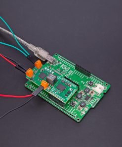
How does it work?
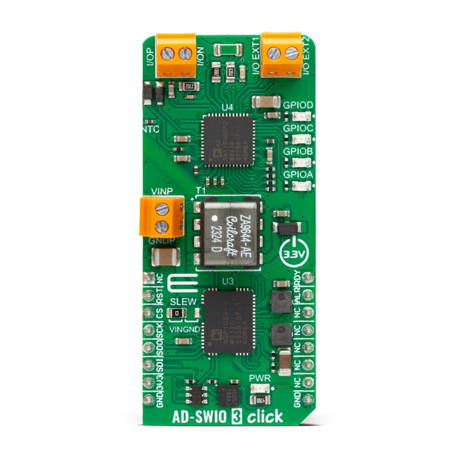
AD-SWIO 3 Click is based on the AD74115H, a single-channel, software-configurable input and output with HART mode, and ADP1034, a 3-channel isolated micropower management unit with seven digital isolators and programmable power control both from Analog Devices. The AD74115H has a single-channel input and output, which can be configured as voltage input, current input, voltage output, current output, digital input, digital output, 2/3/4-wire RTD measurement, or thermocouple measurement input. It features a 16-bit, Σ-Δ analog-to-digital converter (ADC) and a 14-bit digital-to-analog converter (DAC), with a high accuracy 2.5V on-chip reference that can be used both for ADC and DAC.
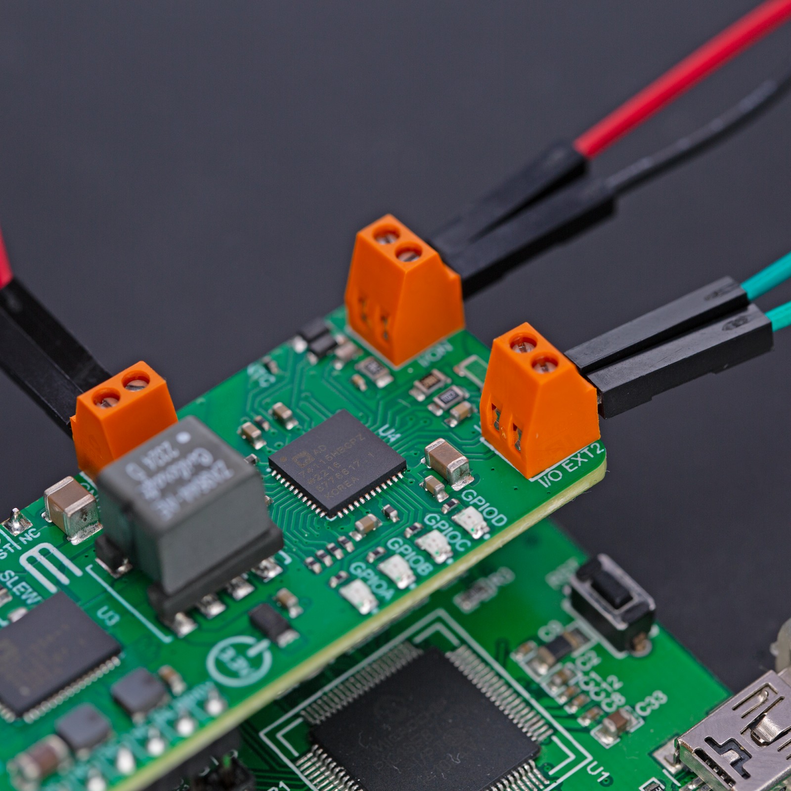
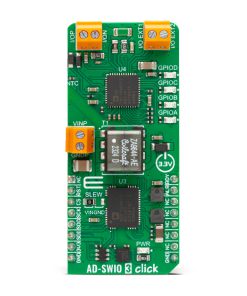
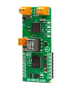
You can connect the desired load to terminals labeled I/OP and I/ON for analog output, analog input, and digital input functions. To apply a stimulus to the two auxiliary high-voltage sense pins, use I/O EXT1 and I/O EXT2 terminals. The resistance measurements can be made between those four terminals, depending on the number of wires RTD. For instance, take 2-wire resistance measurements between the I/OP and I/ON terminals. The integrated HART modem can transmit and receive signals to and from the I/OP terminal. For more info, check the datasheet. Four LEDs (GPIOA, GPIOB, GPIOC, GPIOD) can be configured in several ways to represent digital input, digital output, external or internal conditions, and more. An onboard thermistor is connected to the AD74115H, which can measure the board’s temperature.
The ADP1034 provides power and isolation to the AD74115H. A flyback regulator supply voltage of 24V can be applied over the VINP terminal. You can control the flyback regulator slew rate over the SLEW jumper between the slowest and normal as default. You can also choose the highest by leaving the SLEW pin open. The ZA9644-AED, a flyback transformer from Coilcraft, is used for flyback regulator operation.
AD-SWIO 3 Click uses a standard 4-wire SPI serial interface of the AD74115H through the isolation that provides the ADP1034 to communicate with the host MCU. You can reset the AD74115H over the RST pin. When a new sequence of ADC conversion is ready to be read, the RDY will be asserted. Also, the alert ALR pin will be asserted when the alert condition is met. All those lines pass through an isolation barrier of the ADP1034 on its way to the host MCU.
This Click board™ can be operated only with a 3.3V logic voltage level. The board must perform appropriate logic voltage level conversion before using MCUs with different logic levels. Also, this Click board™ comes equipped with a library containing easy-to-use functions and an example code that can be used as a reference for further development.
Specifications
Type
ADC-DAC,Isolators
Applications
Can be used for the development of isolated industrial control systems, process control, factory automation, building control systems, and more
On-board modules
AD74115H – software-configurable input and output with HART mode from Analog Devices
ADP1034 – isolated micropower management unit with seven digital isolators and programmable power control from Analog Devices
Key Features
Software-configurable, voltage, current, and digital input and output, 2/3/4-wire RTD measurement, auxiliary high voltage sense pins, 16-bit ADC, 14-bit DAC, integrated HART modem, unipolar and bipolar capability, internal temperature sensor, integrated flyback power switch, selectable slew rate, and more
Interface
SPI
Feature
ClickID
Compatibility
mikroBUS™
Click board size
L (57.15 x 25.4 mm)
Input Voltage
3.3V,External
Pinout diagram
This table shows how the pinout on AD-SWIO 3 Click corresponds to the pinout on the mikroBUS™ socket (the latter shown in the two middle columns).
Onboard settings and indicators
Label | Name | Default | Description |
---|---|---|---|
LD1 | PWR | – | Power LED Indicator |
LD2-LD5 | GPIOA-GPIOD | – | User-Configurable LED Indicators |
JP1 | SLEW | Left | Slew Rate Selection VIN/GND: Left position VIN, Right position GND |
AD-SWIO 3 Click electrical specifications
Description | Min | Typ | Max | Unit |
---|---|---|---|---|
Supply Voltage | – | 3.3 | – | V |
Flyback Regulator Supply Voltage | – | 24 | – | V |
ADC Resolution | – | – | 16 | bit |
DAC Resolution | – | – | 14 | bit |
Software Support
We provide a library for the AD-SWIO 3 Click as well as a demo application (example), developed using MIKROE compilers. The demo can run on all the main MIKROE development boards.
Package can be downloaded/installed directly from NECTO Studio Package Manager (recommended), downloaded from our LibStock™ or found on Mikroe github account.
Library Description
This library contains API for AD-SWIO 3 Click driver.
Key functions
-
adswio3_get_voltage_input
This function reads the raw ADC value and converts them to a proportional voltage level measured by the voltage between the I/OP and I/ON screw terminals. -
adswio3_get_diag_res
This function is used to read the desired diagnostic conversion results. -
adswio3_set_adc_cnv
This function is used to control the ADC conversions that must be performed.
Example Description
This library contains API for the AD-SWIO 3 Click driver for measurements of the analog output, analog input, digital input, resistance temperature detector (RTD), and thermocouple measurements.
void application_task ( void )
{
float ntc_temp = 0, iop_ion_vtg = 0;
if ( ADSWIO3_OK == adswio3_get_ntc_temp( &adswio3, ADSWIO3_DIAG_RESULT_SEL_3, &ntc_temp ) )
{
log_printf( &logger, " NTC Temperature: %.2f degCrn", ntc_temp );
Delay_ms( 100 );
}
if ( ADSWIO3_OK == adswio3_get_voltage_input( &adswio3, 0, &iop_ion_vtg ) )
{
log_printf( &logger, "IOP/ION Voltage: %.3f Vrn", iop_ion_vtg );
Delay_ms( 100 );
}
log_printf( &logger, "_________________________rn" );
Delay_ms( 1000 );
}
The full application code, and ready to use projects can be installed directly from NECTO Studio Package Manager (recommended), downloaded from our LibStock™ or found on Mikroe github account.
Other Mikroe Libraries used in the example:
- MikroSDK.Board
- MikroSDK.Log
- Click.ADSWIO3
Additional notes and informations
Depending on the development board you are using, you may need USB UART click, USB UART 2 Click or RS232 Click to connect to your PC, for development systems with no UART to USB interface available on the board. UART terminal is available in all MIKROE compilers.
mikroSDK
This Click board™ is supported with mikroSDK – MIKROE Software Development Kit. To ensure proper operation of mikroSDK compliant Click board™ demo applications, mikroSDK should be downloaded from the LibStock and installed for the compiler you are using.
For more information about mikroSDK, visit the official page.