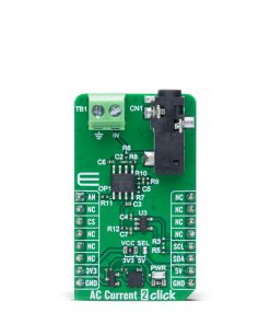
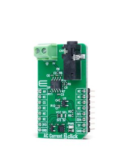
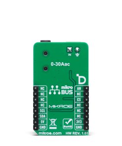
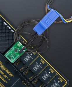
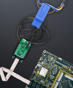
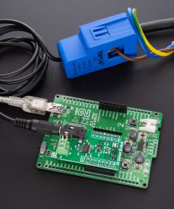
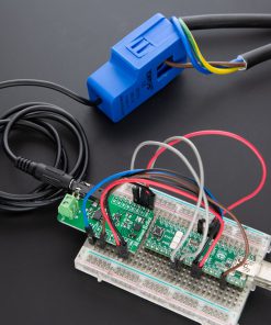
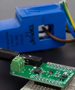
DO NOT TOUCH THE BOARD WHILE THE LOAD IS CONNECTED!
Note: This Click board™ needs to be used by trained personnel only while applying high voltages. Special care should be taken when working with hazardous voltage levels.
How does it work?
AC Current 2 Click is an add-on board made for the safe and accurate measurement of alternating current (AC) running through a conductor. It is specifically designed to work with a non-invasive current sensor, like AC Current Sensor – 30A that MIKROE offers, allowing the current in high-voltage installations such as mains wiring to be monitored without direct electrical contact. Thanks to its galvanic isolation and non-intrusive design, this board is ideal for applications such as current consumption monitoring, safety systems, and general AC current measurement where user safety and circuit integrity are priorities. The board is equipped with a 3.5mm jack connector and a connection terminal, offering flexibility depending on how the sensing probe needs to be connected in the user’s application.
The sensing probe operates on the principle of electromagnetic induction, much like a transformer, but without a primary winding. Instead, the AC current flowing through the conductor naturally generates the electromagnetic field necessary for sensing. The probe’s core is split, allowing it to clamp around the cable easily and measure current without modifying or affecting the electrical system. To maintain signal quality, the incoming voltage from the sensor passes through an RC filter that suppresses electromagnetic interference (EMI) and radio-frequency noise. After filtering, the signal is amplified by the MCP607 operational amplifier from Microchip, a rail-to-rail OpAmp with extremely low offset voltage and low bias current, ensuring that the measurement remains accurate and stable across different conditions.
For digital signal processing, the amplified voltage is then converted into a digital form by the MCP3221, a 12-bit successive approximation analog-to-digital converter (ADC) that communicates with the host MCU via a standard I2C interface. In addition to the digital output, AC Current 2 Click also offers a direct analog signal path via AN pin, enabling users to access the amplified signal without conversion if needed.
This Click board™ can operate with either 3.3V or 5V logic voltage levels selected via the VCC SEL jumper. This way, both 3.3V and 5V capable MCUs can use the communication lines properly. Also, this Click board™ comes equipped with a library containing easy-to-use functions and an example code that can be used as a reference for further development.
Specifications
Type
Current sensor
Applications
Ideal for current consumption monitoring, high-voltage system diagnostics, safety equipment, and general AC current measurements
On-board modules
MCP607 – rail-to-rail OpAmp from Microchip | MCP3221 12-bit ADC from Microchip
Key Features
Non-invasive AC current measurement based on electromagnetic induction principle, galvanic isolation for safe high-voltage monitoring, integrated RC filter for EMI and RF noise suppression, flexible probe connection through 3.5mm jack connector or terminal block, output in analog and digital form, and more
Interface
Analog,I2C
Feature
ClickID
Compatibility
mikroBUS™
Click board size
M (42.9 x 25.4 mm)
Input Voltage
3.3V or 5V
Pinout diagram
This table shows how the pinout on AC Current 2 Click corresponds to the pinout on the mikroBUS™ socket (the latter shown in the two middle columns).
Onboard settings and indicators
Label | Name | Default | Description |
---|---|---|---|
LD1 | PWR | – | Power LED Indicator |
JP1 | VCC SEL | Left | Power Voltage Level Selection 3V3/5V: Left position 3V3, Right position 5V |
AC Current 2 Click electrical specifications
Description | Min | Typ | Max | Unit |
---|---|---|---|---|
Supply Voltage | 3.3 | – | 5 | V |
Current Sensing Range | – | – | 30 | A |
Software Support
AC Current 2 Click demo application is developed using the NECTO Studio, ensuring compatibility with mikroSDK‘s open-source libraries and tools. Designed for plug-and-play implementation and testing, the demo is fully compatible with all development, starter, and mikromedia boards featuring a mikroBUS™ socket.
Example Description
This example demonstrates how to use the AC Current 2 Click board for reading the measurements from the AC Current sensor attached to the Click board input.
Key Functions
accurrent2_cfg_setup
This function initializes Click configuration structure to initial values.accurrent2_init
This function initializes all necessary pins and peripherals used for this Click board.accurrent2_read_current
This function reads the current measurement from the AC Current sensor (30A/1V).
Application Init
Initializes the driver and logger.
Application Task
Continuously reads the AC current value and logs the measured data in amperes (A).
Application Output
This Click board can be interfaced and monitored in two ways:
- Application Output – Use the “Application Output” window in Debug mode for real-time data monitoring. Set it up properly by following this tutorial.
- UART Terminal – Monitor data via the UART Terminal using a USB to UART converter. For detailed instructions, check out this tutorial.
Additional Notes and Information
The complete application code and a ready-to-use project are available through the NECTO Studio Package Manager for direct installation in the NECTO Studio. The application code can also be found on the MIKROE GitHub account.