6DOF IMU 26 Click
R2,800.00 ex. VAT
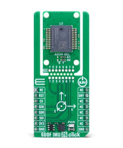
6DOF IMU 26 Click is a compact add-on board designed to detect and measure angular rate and linear acceleration across three axes. This board features the SCH16T-K01, a high-performance 6DOF sensor that integrates a 3-axis gyroscope and a 3-axis accelerometer from muRata. The board features a selectable measurement range for both sensors, low-pass filtering from 13Hz to 370Hz, and a 4-wire SPI interface. It also includes the innovative Click Snap design, enabling sensor separation and autonomous operation, with configurable SPI address and data-ready interrupt output. This Click board™ is ideal for inertial navigation systems, robotic motion tracking, machine control, UAV stabilization, and other applications in demanding environments.
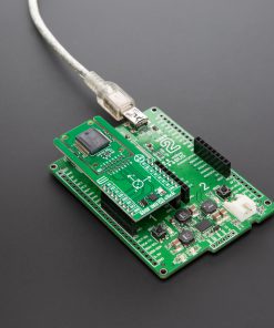
6DOF IMU 26 Click is fully compatible with the mikroBUS™ socket and can be used on any host system supporting the mikroBUS™ standard. It comes with the mikroSDK open-source libraries, offering unparalleled flexibility for evaluation and customization. What sets this Click board™ apart is the groundbreaking ClickID feature, enabling your host system to seamlessly and automatically detect and identify this add-on board, alongside a Click Snap feature introducing a new level of flexibility and ease of use.
Stock: Lead-time applicable.
| 5+ | R2,660.00 |
| 10+ | R2,590.00 |
| 15+ | R2,520.00 |
| 20+ | R2,450.00 |
How does it work?
6DOF IMU 26 Click is based on the SCH16T-K01, a high-performance six-degrees-of-freedom (6DOF) motion sensor from muRata. This device combines a 3-axis gyroscope and a 3-axis accelerometer into a single package, communicating via a digital SPI interface for efficient data transfer. Designed to deliver precision and stability even under demanding conditions, the SCH16T-K01 supports a wide range of configurable options that enhance its adaptability across various applications. The gyroscope offers an in-application selectable measurement range from 300 degrees per second down to 62.5 degrees per second, while the accelerometer supports a selectable range from ±80 m/s² down to ±15 m/s², with a typical default dynamic range of up to ±260 m/s². The sensor also integrates output interpolation and decimation options, allowing flexible data handling and processing tailored to specific needs.
.jpg)
The SCH16T-K01 also features adjustable low-pass filters for both angular rate and acceleration, with cut-off frequencies ranging from 13Hz to 370Hz, ensuring clean signal acquisition even in noisy environments. Built to meet the rigorous AEC-Q100 automotive qualification standard, the SCH16T-K01 is ideal for use in inertial measurement units (IMUs), inertial navigation and positioning systems, dynamic inclination detection, machine control and guidance, robotic platforms, and unmanned aerial vehicles (UAVs), making 6DOF IMU 26 Click a versatile solution for motion tracking in harsh or mission-critical environments.
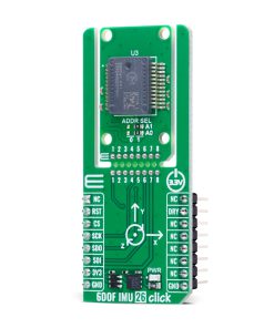
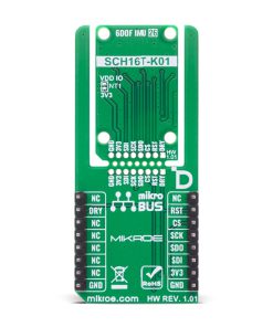
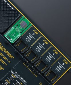
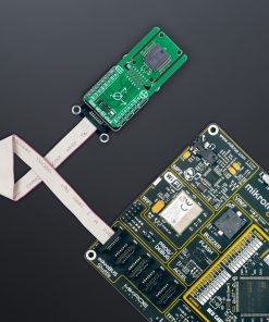
This Click board™ is designed in a unique format supporting the newly introduced MIKROE feature called “Click Snap.” Unlike the standardized version of Click boards, this feature allows the main sensor area to become movable by breaking the PCB, opening up many new possibilities for implementation. Thanks to the Snap feature, the SCH16T-K01 can operate autonomously by accessing its signals directly on the pins marked 1-8. Additionally, the Snap part includes a specified and fixed screw hole position, enabling users to secure the Snap board in their desired location.
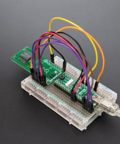
This Click board™ establishes communication with the host MCU using a 4-wire SPI interface with maximum clock frequency of 10MHz, ensuring reliable and high-speed data transfer. The SPI address of the SCH16T-K01 can be easily configured via onboard jumpers marked ADDR SEL in the Snap area, allowing multiple devices to coexist on the same bus. In addition to the interface pins, the 6DOF IMU 26 Click also uses the RST pin for resetting the SCH16T-K01, and DRY pin as data ready signal that ) outputs an interrupt signal for host MCU when the internal output registers (gyroscope + accelerometer) have been updated.
This Click board™ can be operated only with a 3.3V logic voltage level. The board must perform appropriate logic voltage level conversion before using MCUs with different logic levels. It also comes equipped with a library containing functions and example code that can be used as a reference for further development.
Click Snap
Click Snap is an innovative feature of our standardized Click add-on boards, designed to bring greater flexibility and optimize your prototypes. By simply snapping the PCB along predefined lines, you can easily detach the main sensor/IC/module area, reducing the overall size, weight, and power consumption – ideal for the final phase of prototyping. For more details about Click Snap, visit the official page dedicated to this feature.
Specifications
Type
Motion
Applications
Ideal for inertial navigation systems, robotic motion tracking, machine control, UAV stabilization, and other applications in demanding environments
On-board modules
SCH16T-K01 – 6-DOF XYZ-axis gyroscope and accelerometer from muRata
Key Features
6DOF motion sensing, 3-axis gyroscope and accelerometer integration, digital SPI interface, in-application selectable measurement ranges, angular rate and acceleration low-pass filters, output interpolation and decimation options, Data Ready interrupt output, Click Snap support with detachable sensor section, and more
Interface
SPI
Feature
Click Snap,ClickID
Compatibility
mikroBUS™
Click board size
L (57.15 x 25.4 mm)
Input Voltage
3.3V
Pinout diagram
This table shows how the pinout on 6DOF IMU 26 Click corresponds to the pinout on the mikroBUS™ socket (the latter shown in the two middle columns).
| Notes | Pin | Pin | Notes | ||||
|---|---|---|---|---|---|---|---|
| NC | 1 | AN | PWM | 16 | NC | ||
| Reset / ID SEL | RST | 2 | RST | INT | 15 | DRY | Data-Ready Output |
| SPI Select / ID COMM | CS | 3 | CS | RX | 14 | NC | |
| SPI Clock | SCK | 4 | SCK | TX | 13 | NC | |
| SPI Data OUT | SDO | 5 | MISO | SCL | 12 | NC | |
| SPI Data IN | SDI | 6 | MOSI | SDA | 11 | NC | |
| Power Supply | 3.3V | 7 | 3.3V | 5V | 10 | NC | |
| Ground | GND | 8 | GND | GND | 9 | GND | Ground |
Onboard settings and indicators
| Label | Name | Default | Description |
|---|---|---|---|
| LD1 | PWR | – | Power LED Indicator |
| JP1-JP2 | ADDR SEL | Right | SPI Address Selection 0/1: Left position 0, Right position 1 |
6DOF IMU 26 Click electrical specifications
| Description | Min | Typ | Max | Unit |
|---|---|---|---|---|
| Supply Voltage | – | 3.3 | – | V |
| Gyroscope Measurement Range | ±300 | – | ±62.5 | °/s |
| Gyroscope Sensitivity | – | 0.0003 | 0.006 | (°/s)/(m/s2) |
| Accelerometer Measurement Range | ±80 | – | ±15 | m/s2 |
| Accelerometer Sensitivity | – | 3200 | – | LSB/(m/s2) |
Software Support
6DOF IMU 26 Click demo application is developed using the NECTO Studio, ensuring compatibility with mikroSDK‘s open-source libraries and tools. Designed for plug-and-play implementation and testing, the demo is fully compatible with all development, starter, and mikromedia boards featuring a mikroBUS™ socket.
Example Description
This example demonstrates the use of the 6DOF IMU 26 Click board, which provides 3-axis accelerometer and 3-axis gyroscope measurements, as well as temperature data. The example initializes the device and continuously logs sensor readings.
Key Functions
c6dofimu26_cfg_setupThis function initializes Click configuration structure to initial values.c6dofimu26_initThis function initializes all necessary pins and peripherals used for this Click board.c6dofimu26_default_cfgThis function executes a default configuration of 6DOF IMU 26 Click board.c6dofimu26_get_dataThis function reads the accelerometer, gyroscope, and temperature data.
Application Init
Initializes the logger and configures the 6DOF IMU 26 Click board. Sets up SPI communication and applies the default configuration.
Application Task
Continuously reads and logs acceleration (g), gyroscope (dps), and temperature (degC) values from the sensor.
Application Output
This Click board can be interfaced and monitored in two ways:
- Application Output – Use the “Application Output” window in Debug mode for real-time data monitoring. Set it up properly by following this tutorial.
- UART Terminal – Monitor data via the UART Terminal using a USB to UART converter. For detailed instructions, check out this tutorial.
Additional Notes and Information
The complete application code and a ready-to-use project are available through the NECTO Studio Package Manager for direct installation in the NECTO Studio. The application code can also be found on the MIKROE GitHub account.
Resources
Downloads
| Weight | 19 g |
|---|---|
| Brand | MikroElektronika |