How does it work?
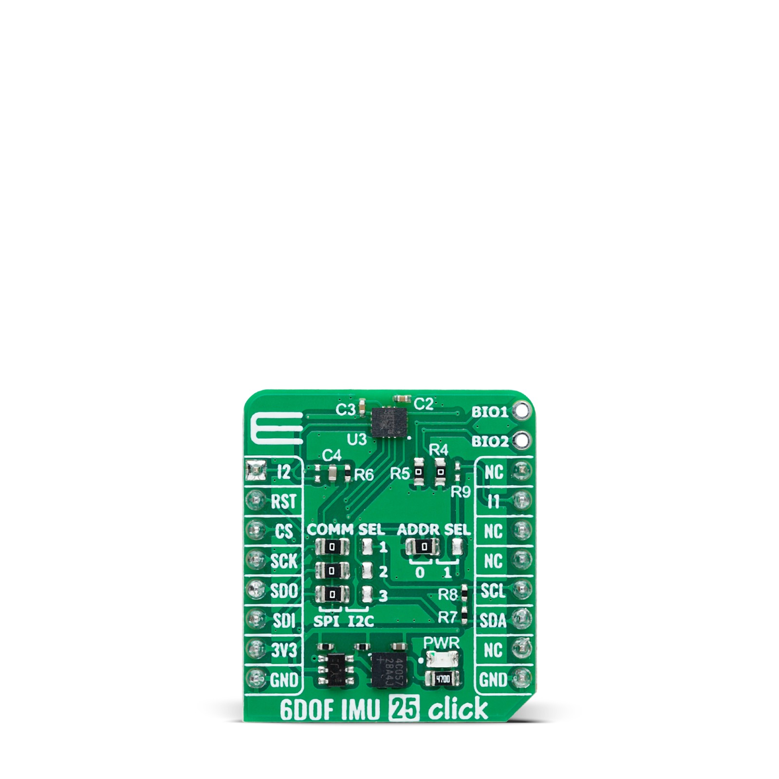
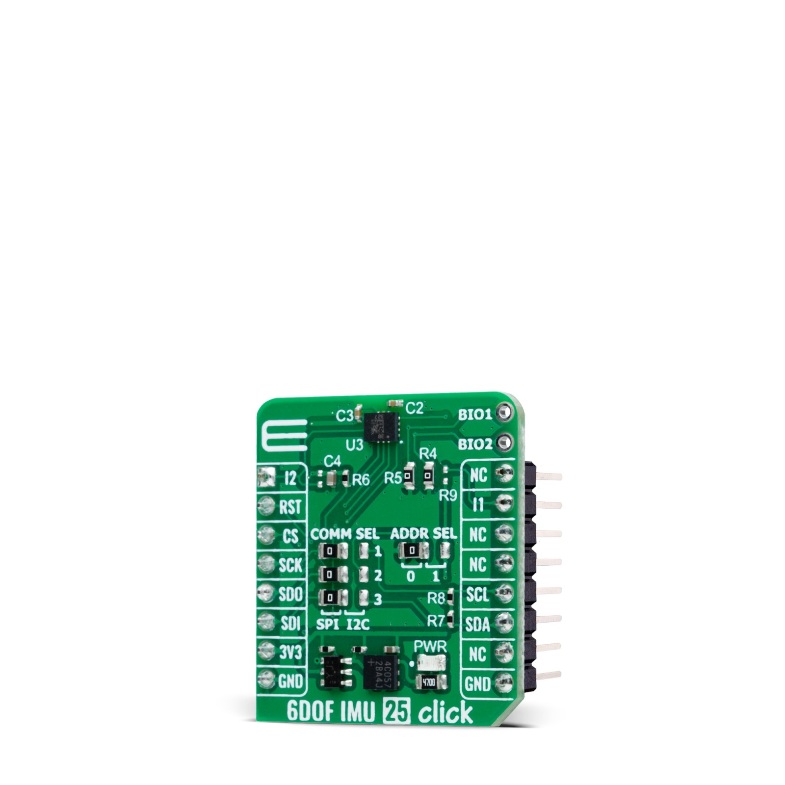
6DOF IMU 25 Click is based on the ST1VAFE6AX, an advanced biosensor from STMicroelectronics that integrates a vertical analog front-end (vAFE) for biopotential signal detection with a high-performance 6-axis inertial measurement unit (IMU). This dual-function device combines a 3-axis digital accelerometer (with selectable full-scale ranges of ±2/±4/±8/±16 g) and a 3-axis digital gyroscope (offering ranges of ±125/±250/±500/±1000/±2000/±4000 dps) for precise motion tracking. The sensor also includes state-of-the-art features like a finite state machine (FSM), sensor fusion low power (SFLP), adaptive self-configuration (ASC), and a machine learning core (MLC) with AI-capable filters, ensuring versatile performance across a range of applications.
The ST1VAFE6AX’s innovative vAFE channel is optimized for low-power operation and supports configurable input impedance, enabling easy acquisition of biopotential signals from BIO pads alongside motion data. This synchronized integration ensures context-aware analysis directly at the sensor level, minimizing latency and power consumption. By leveraging its embedded features like FSM and MLC, the sensor enables standalone processing, reducing the workload on the microcontroller and supporting efficient edge computing. The result is a compact, versatile solution capable of performing advanced signal processing and machine learning tasks in resource-constrained environments.
A built-in 4.5KB FIFO buffer with compression and dynamic data allocation further enhances system power efficiency, allowing for optimized data handling and reduced processor intervention. The combined capabilities of the vAFE and IMU make 6DOF IMU 25 Click ideal for applications requiring precise biopotential signal monitoring and motion analysis such as heart rate and pulse monitoring, electrocardiograms (ECG), activity tracking, and well-being in digital healthcare, as well as wearable and portable devices.
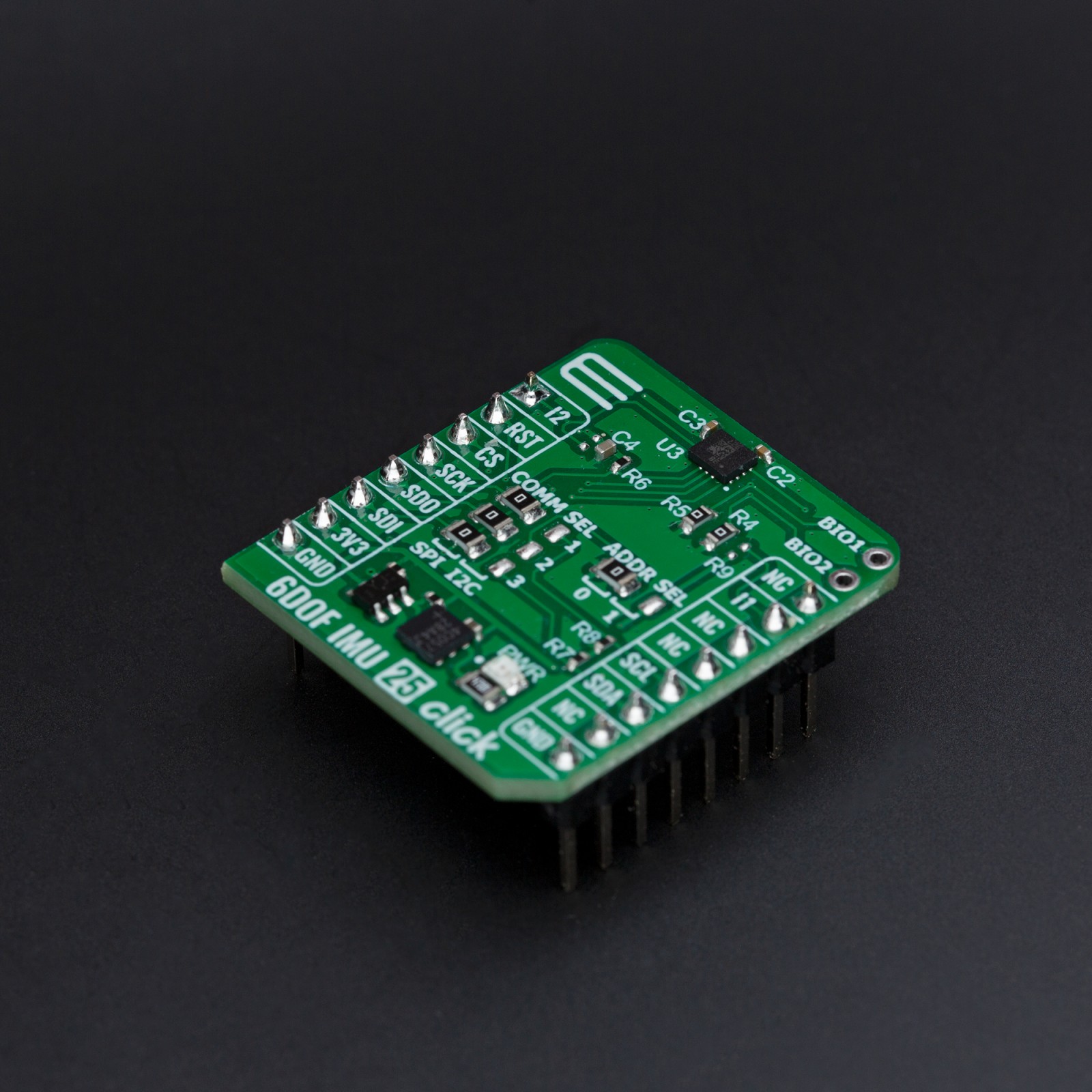
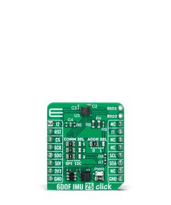
Biopotential and motion data are accessed through the I2C or SPI interface, with a maximum frequency of 1MHz for I2C and 10MHz for SPI communication. The selection is made by positioning SMD jumpers labeled COMM SEL appropriately. Note that all the jumpers’ positions must be on the same side, or the Click board™ may become unresponsive. While the I2C interface is selected, the ST1VAFE6AX allows the least significant bit (LSB) of its I2C address to be chosen using the SMD jumper labeled ADDR SEL.
This board also possesses two interrupts, I1 and I2, routed to, where, by default, the INT and AN pins stand on the mikroBUS™ socket, entirely programmed by the user through a serial interface. The event-detection interrupts enable efficient and reliable motion tracking and context awareness, implementing hardware recognition of free-fall events, 6D orientation, click and double-click sensing, activity or inactivity, stationary/motion detection, and wake-up events.
This Click board™ can be operated only with a 3.3V logic voltage level. The board must perform appropriate logic voltage level conversion before using MCUs with different logic levels. It also comes equipped with a library containing functions and example code that can be used as a reference for further development.
Specifications
Type
Motion
Applications
Ideal for heart rate and pulse monitoring, electrocardiograms (ECG), activity tracking, and wearable device applications
On-board modules
ST1VAFE6AX – biosensor with vAFE (vertical analog front-end) for biopotential signals and 6-axis IMU (inertial measurement unit) with AI and sensor fusion from STMicroelectronics
Key Features
Vertical analog front-end (vAFE) for biopotential signal acquisition, 6-axis IMU, features finite state machine (FSM), adaptive self-configuration (ASC), and machine learning core (MLC) with AI-capable filters, 4.5KB FIFO buffer, selectable interface, event detection, and more
Interface
I2C,SPI
Feature
ClickID
Compatibility
mikroBUS™
Click board size
S (28.6 x 25.4 mm)
Input Voltage
3.3V
Pinout diagram
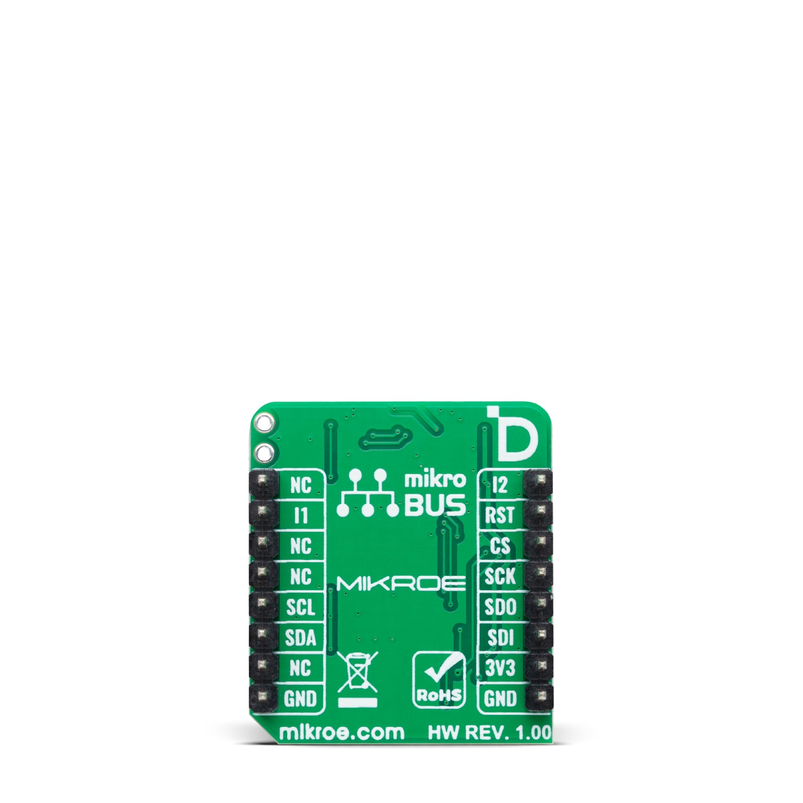
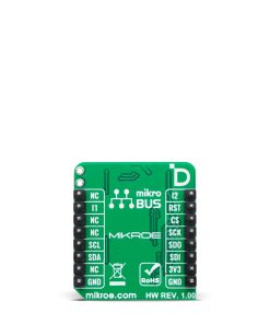
This table shows how the pinout on 6DOF IMU 25 Click corresponds to the pinout on the mikroBUS™ socket (the latter shown in the two middle columns).
Onboard settings and indicators
Label | Name | Default | Description |
---|---|---|---|
LD1 | PWR | – | Power LED Indicator |
JP1-JP3 | COMM SEL | Left | Communication Interface Selection SPI/I2C: Left position SPI, Right position I2C |
JP4 | ADDR SEL | Left | I2C Address Selection 0/1: Left position 0, Right position 1 |
6DOF IMU 25 Click electrical specifications
Description | Min | Typ | Max | Unit |
---|---|---|---|---|
Supply Voltage | – | 3.3 | – | V |
Acceleration Measurement Range | ±2 | – | ±16 | g |
Acceleration Sensitivity | 0.061 | – | 0.488 | mg/LSB |
Angular Rate Measurement Range | ±125 | – | ±4000 | dps |
Angular Rate Sensitivity | 4.375 | – | 140 | mdps/LSB |
Software Support
We provide a library for the 6DOF IMU 25 Click as well as a demo application (example), developed using MIKROE compilers. The demo can run on all the main MIKROE development boards.
Package can be downloaded/installed directly from NECTO Studio Package Manager (recommended), downloaded from our LibStock™ or found on MIKROE github account.
Library Description
This library contains API for 6DOF IMU 25 Click driver.
Key functions
-
c6dofimu25_get_int1_pin
This function returns the interrupt 1 pin logic state. -
c6dofimu25_get_data
This function reads the accelerometer, gyroscope, and temperature measurement data. -
c6dofimu25_set_accel_fsr
This function sets the accel measurement full scale range.
Example Description
This example demonstrates the use of 6DOF IMU 25 Click by reading and displaying the accelerometer and gyroscope data (X, Y, and Z axis) as well as a temperature measurement in degrees Celsius.
void application_task ( void )
{
c6dofimu25_data_t meas_data;
if ( c6dofimu25_get_int1_pin ( &c6dofimu25 ) )
{
if ( C6DOFIMU25_OK == c6dofimu25_get_data ( &c6dofimu25, &meas_data ) )
{
log_printf( &logger, " Accel X: %.3f grn", meas_data.accel.x );
log_printf( &logger, " Accel Y: %.3f grn", meas_data.accel.y );
log_printf( &logger, " Accel Z: %.3f grn", meas_data.accel.z );
log_printf( &logger, " Gyro X: %.1f dpsrn", meas_data.gyro.x );
log_printf( &logger, " Gyro Y: %.1f dpsrn", meas_data.gyro.y );
log_printf( &logger, " Gyro Z: %.1f dpsrn", meas_data.gyro.z );
log_printf( &logger, " Temperature: %.2f degCrnn", meas_data.temperature );
}
}
}
The full application code, and ready to use projects can be installed directly from NECTO Studio Package Manager (recommended), downloaded from our LibStock™ or found on MIKROE github account.
Other MIKROE Libraries used in the example:
- MikroSDK.Board
- MikroSDK.Log
- Click.6DOFIMU25
Additional notes and informations
Depending on the development board you are using, you may need USB UART click, USB UART 2 Click or RS232 Click to connect to your PC, for development systems with no UART to USB interface available on the board. UART terminal is available in all MIKROE compilers.
mikroSDK
This Click board™ is supported with mikroSDK – MIKROE Software Development Kit. To ensure proper operation of mikroSDK compliant Click board™ demo applications, mikroSDK should be downloaded from the LibStock and installed for the compiler you are using.
For more information about mikroSDK, visit the official page.