How does it work?
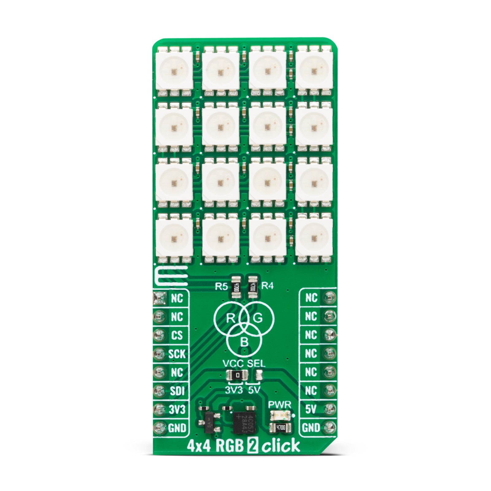
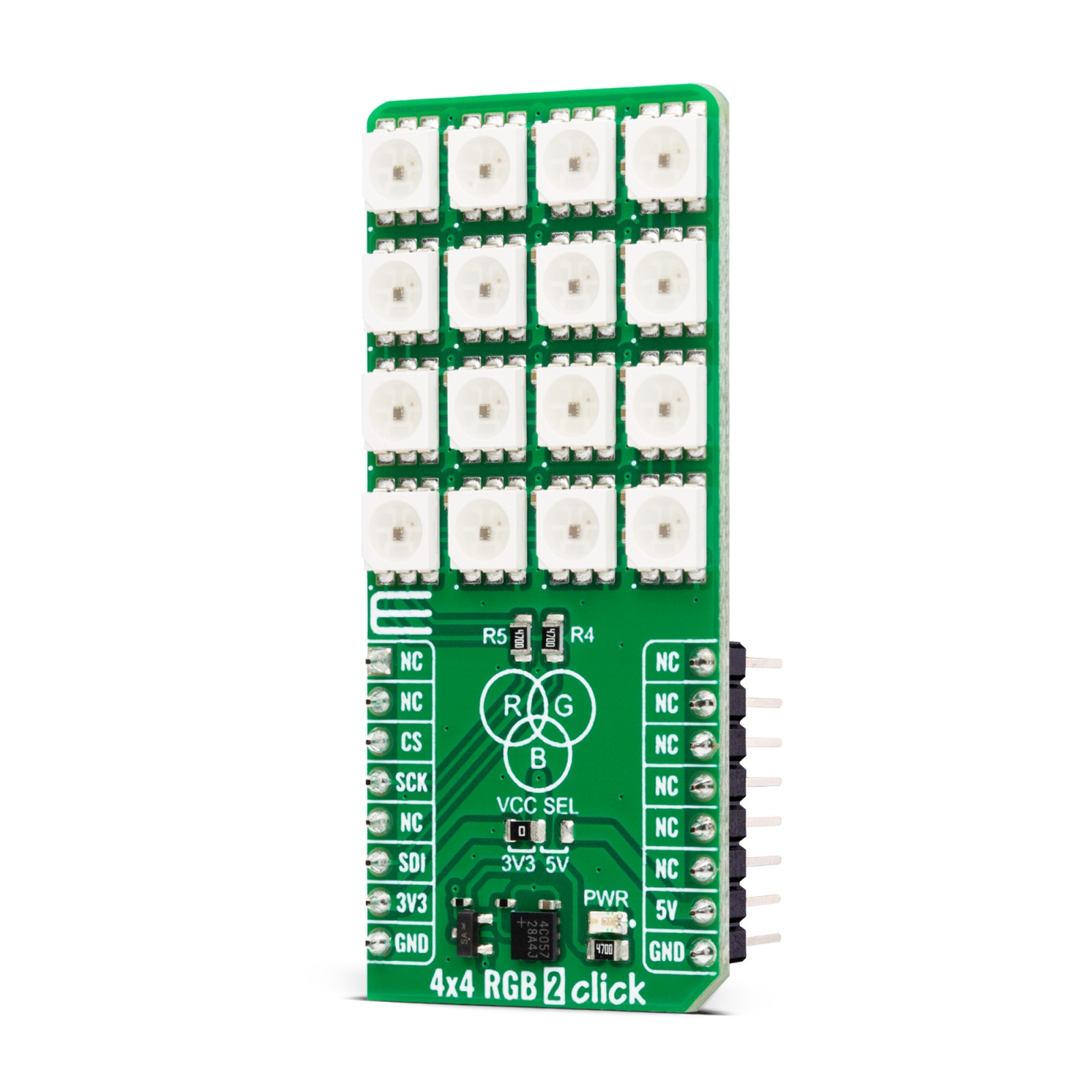
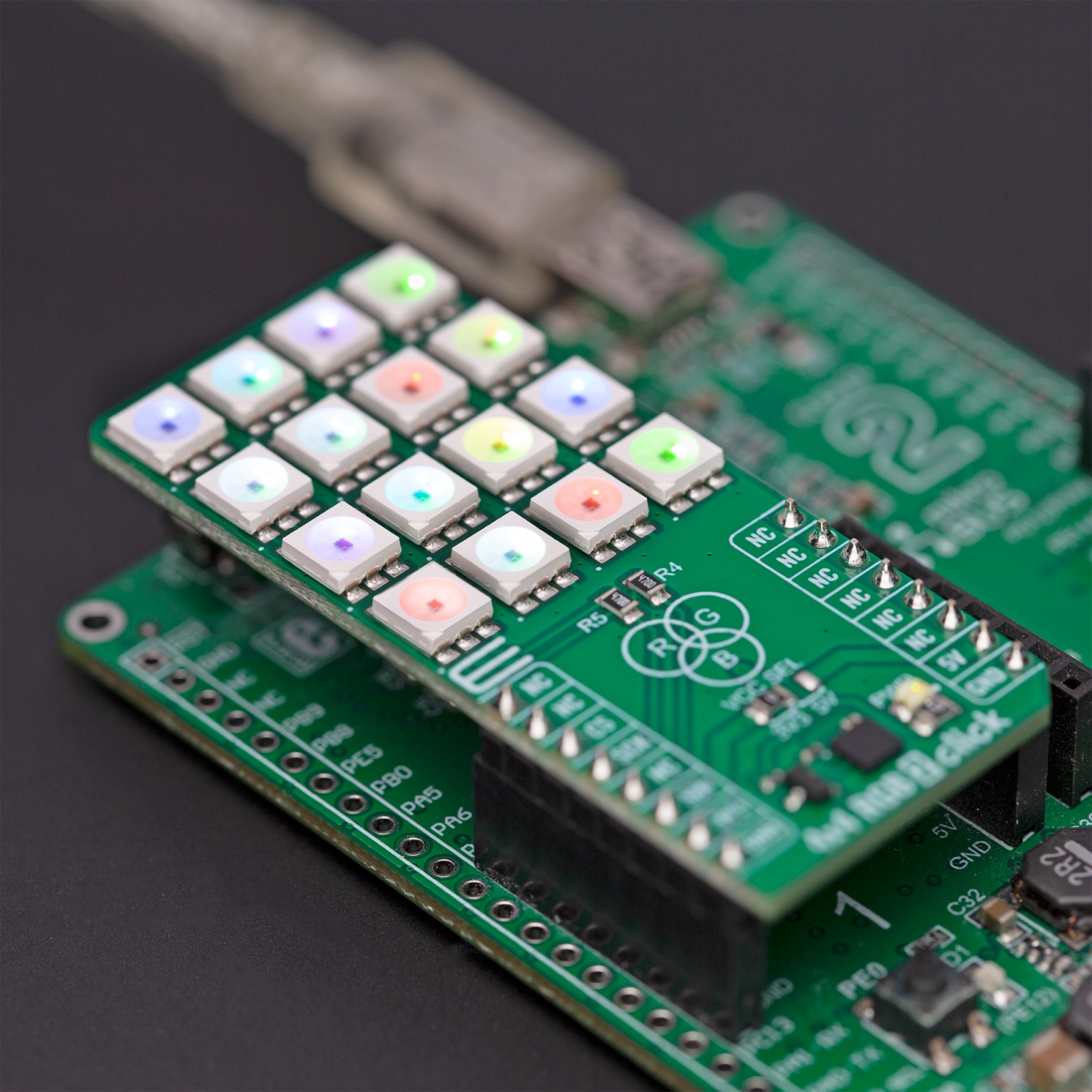
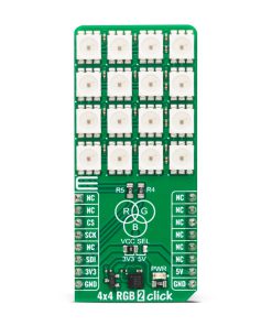
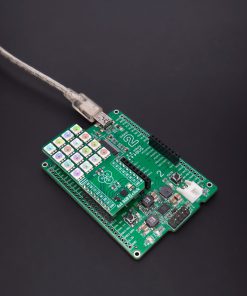
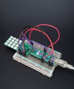
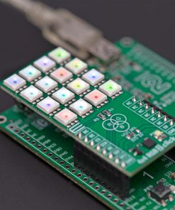
4×4 EGB 2 Click is based on 16 IN-PC55TBTRGB, RGB LEDs with an integrated IC from Inolux. The LED contains a signal decoding module, a data buffer, a built-in current circuit, and an RC oscillator in the same 5050 packages forming a color-mixing uniformity and consistency. The LEDs can maintain a static image, thus, making the perfect choice for developing an LED screen. Some other features that these LEDs have are built-in support for uninterrupted oscillation PWM, double data transmission, self-detection function-specific signal, three constant current drives, and more.
The 4×4 RGB 2 Click uses a two-wire synchronous transmission to communicate with the host MCU, routed to the SCK and the SDI pins of the mikroBUS™ socket. The maximum input serial data frequency is 30MHz. The data transmission goes from the host MCU through every single LED until the last one in a cascade manner, where the only limit is the number of the LEDs on this Click board™. The maximum LED output current is 20mA, while the LEDs’ light intensity, depending on the current, varies from 300mcd at the lowest for Blue to 1500mcd at the highest for Green.
Although the chain could be bigger, this is not enabled on the 4×4 RGB 2 Click. The length of the chain can be limited only by the communication speed required to scan through all the LED devices in order to maintain a reasonable refresh speed.
This Click board™ can operate with either 3.3V or 5V logic voltage levels selected via the VCC SEL jumper. This way, both 3.3V and 5V capable MCUs can use the communication lines properly. However, the Click board™ comes equipped with a library containing easy-to-use functions and an example code that can be used, as a reference, for further development.
Specifications
Type
LED Matrix
Applications
Can be used for the development of LED-shaped screens, color LED string light, scene lighting, and more
On-board modules
IN-PC55TBTRGB – RGB LED with an integrated IC from Inolux
Key Features
Intelligent LEDs, high brightness, built-in support uninterrupted oscillation PWM output, 8-bit (256) color, 5-bit (32) brightness, double data transmission, constant current drive for all channels, self-detection function-specific signal, and more
Interface
SPI
Feature
ClickID
Compatibility
mikroBUS™
Click board size
L (57.15 x 25.4 mm)
Input Voltage
3.3V or 5V
Pinout diagram
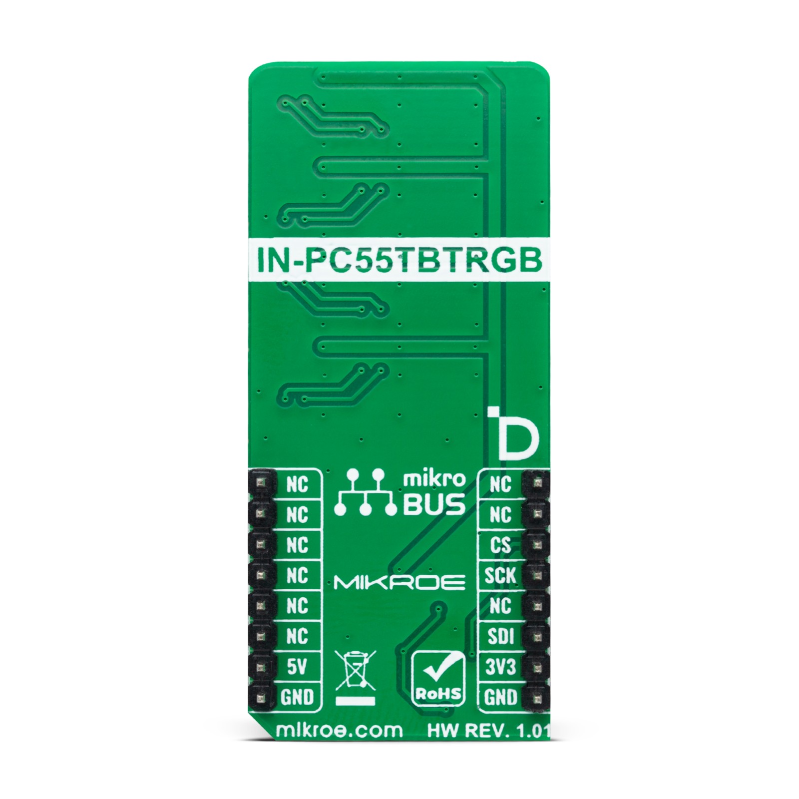
This table shows how the pinout on 4×4 RGB 2 Click corresponds to the pinout on the mikroBUS™ socket (the latter shown in the two middle columns).
Onboard settings and indicators
Label | Name | Default | Description |
---|---|---|---|
LD1 | PWR | – | Power LED Indicator |
JP1 | VCC SEL | Left | Power/Logic Level Voltage Selection 3V3/5V: Left position 3V3, Right position 5V |
4×4 RGB 2 Click electrical specifications
Description | Min | Typ | Max | Unit |
---|---|---|---|---|
Supply Voltage | 3.3 | – | 5 | V |
Maximum LED Output Current | – | – | 20 | mA |
Software Support
We provide a library for the 4×4 RGB 2 Click as well as a demo application (example), developed using MIKROE compilers. The demo can run on all the main MIKROE development boards.
Package can be downloaded/installed directly from NECTO Studio Package Manager(recommended), downloaded from our LibStock™ or found on Mikroe github account.
Library Description
This library contains API for 4×4 RGB 2 Click driver.
Key functions
-
c4x4rgb2_set_led_color
This function sets the color of the selected led in the led matrix. -
c4x4rgb2_set_led_brightness
This function sets the brightness of the selected led in the led matrix. -
c4x4rgb2_write_led_matrix
This function writes the led matrix data from the click context object.
Example Description
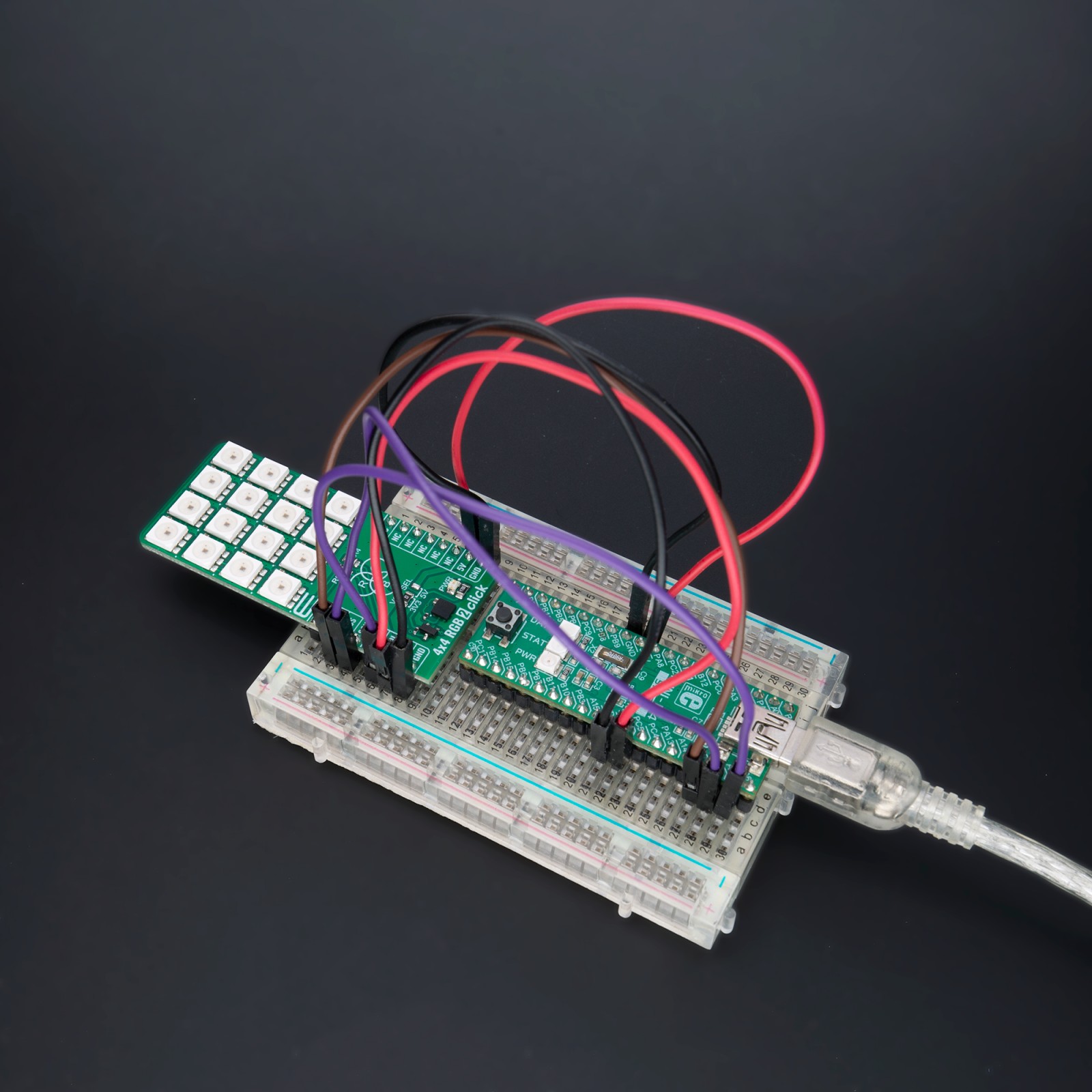
This example demonstrates the use of 4×4 RGB 2 Click board™ by setting all 16 LEDs to different colors and changing the LEDs color every 500 milliseconds.
void application_task ( void )
{
static uint8_t color_num = 0;
for ( uint8_t led_cnt = C4X4RGB2_LED_0; led_cnt <= C4X4RGB2_LED_15; led_cnt++ )
{
c4x4rgb2_set_led_color ( &c4x4rgb2, led_cnt,
color[ ( led_cnt + color_num ) % C4X4RGB2_NUM_COLORS ].rgb );
log_printf( &logger, " LED %u Color: %s - %.6LXrn", ( uint16_t ) led_cnt,
color[ ( led_cnt + color_num ) % C4X4RGB2_NUM_COLORS ].name,
color[ ( led_cnt + color_num ) % C4X4RGB2_NUM_COLORS ].rgb );
}
if ( C4X4RGB2_OK == c4x4rgb2_write_led_matrix ( &c4x4rgb2 ) )
{
log_printf( &logger, " Write LED Matrixrnn" );
Delay_ms ( 500 );
}
if ( ++color_num >= C4X4RGB2_NUM_COLORS )
{
color_num = 0;
}
}
The full application code, and ready to use projects can be installed directly from NECTO Studio Package Manager(recommended), downloaded from our LibStock™ or found on Mikroe github account.
Other Mikroe Libraries used in the example:
- MikroSDK.Board
- MikroSDK.Log
- Click.4x4RGB2
Additional notes and informations
Depending on the development board you are using, you may need USB UART click, USB UART 2 Click or RS232 Click to connect to your PC, for development systems with no UART to USB interface available on the board. UART terminal is available in all MIKROE compilers.
mikroSDK
This Click board™ is supported with mikroSDK – MIKROE Software Development Kit. To ensure proper operation of mikroSDK compliant Click board™ demo applications, mikroSDK should be downloaded from the LibStock and installed for the compiler you are using.
For more information about mikroSDK, visit the official page.