4×4 Key Click
R240.00 ex. VAT
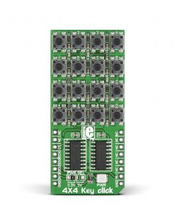
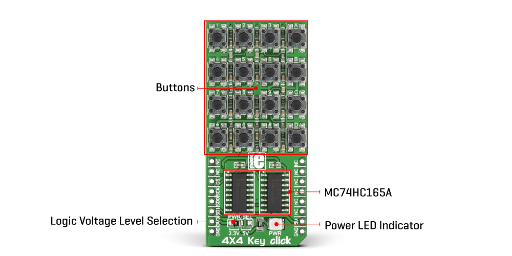
4×4 Click is a compact add-on board that integrates 16 buttons into one design. This board features a 4×4 button keyboard with debounce circuits, and two MC74HC165A, 8-bit parallel-in/serial-out shift registers from onsemi. This 4×4 matrix keyboard allows multiple key presses simultaneously, where each button has its silkscreen marking. This Click board™ makes the perfect solution for Human Machine Interface (HMI) applications.
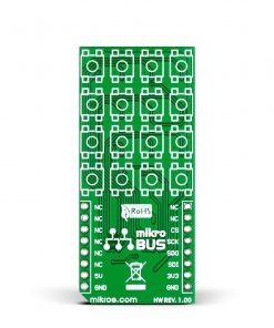
4×4 Click is supported by a mikroSDK compliant library, which includes functions that simplify software development. This Click board™ comes as a fully tested product, ready to be used on a system equipped with the mikroBUS™ socket.
Stock: Lead-time applicable.
| 5+ | R228.00 |
| 10+ | R216.00 |
| 15+ | R204.00 |
| 20+ | R196.32 |
How does it work?
4×4 Click is based on 16 buttons with debounce circuits, and two MC74HC165A, 8-bit parallel-in/serial-out shift registers from onsemi. The rightmost column of the keyboard is marked with letters from A to D, while the other 12 buttons are marked like a telephone keypad, so it is easy to implement this 4×4 Click board to any design. The 16-button output lines go straight to the parallel data inputs of the two shift registers connected in a serial (daisy) chain, thus occupying fewer pins on the host MCU. The shift registers allow you to press all 16 buttons simultaneously, and each will be registered.
The 4X4 Click board uses an SPI serial interface to communicate with the host MCU over the mikroBUS™ socket. In this case, the SPI interface saves as many IO pins of the MCU as possible from 16 buttons using shift registers. The Clock Enable pins of the shift registers are not user configurable and are tied LOW; thus, shift registers are always enabled.
This Click board™ can operate with either 3.3V or 5V logic voltage levels selected via the PWR SEL jumper. This way, both 3.3V and 5V capable MCUs can use the communication lines properly. However, the Click board™ comes equipped with a library containing easy-to-use functions and an example code that can be used, as a reference, for further development.
Specifications
Type
Pushbutton/Switches
Applications
Can be used for a variety of the Human Machine Interface (HMI) applications
On-board modules
MC74HC165A – 8-bit parallel-in/serial-out shift registers from onsemi
Key Features
4×4 keyboard with debounce circuit, pair of shift registers to minimize the IO pins usage, allows for multiple key presses (all 16 buttons simultaneously), SPI interface, low power consumption, selectable power supply, and more
Interface
SPI
Feature
No ClickID
Compatibility
mikroBUS™
Click board size
L (57.15 x 25.4 mm)
Input Voltage
3.3V or 5V
Pinout diagram
This table shows how the pinout on 4×4 Key Click corresponds to the pinout on the mikroBUS™ socket (the latter shown in the two middle columns).
| Notes | Pin | Pin | Notes | ||||
|---|---|---|---|---|---|---|---|
| NC | 1 | AN | PWM | 16 | NC | ||
| NC | 2 | RST | INT | 15 | NC | ||
| SPI Chip Select | CS | 3 | CS | RX | 14 | NC | |
| SPI Clock | SCK | 4 | SCK | TX | 13 | NC | |
| SPI Data OUT | SDO | 5 | MISO | SCL | 12 | NC | |
| SPI Data IN | SDI | 6 | MOSI | SDA | 11 | NC | |
| Power Supply | 3.3V | 7 | 3.3V | 5V | 10 | 5V | Power Supply |
| Ground | GND | 8 | GND | GND | 9 | GND | Ground |
Onboard settings and indicators
| Label | Name | Default | Description |
|---|---|---|---|
| LD1 | PWR | – | Power LED Indicator |
| JP1 | PWR SEL | Left | Logic Level Voltage Selection 3V3/5V: Left position 3V3, Right position 5V |
4×4 Key Click electrical specifications
| Description | Min | Typ | Max | Unit |
|---|---|---|---|---|
| Supply Voltage | 3.3 | – | 5 | V |
Software Support
We provide a library for the 4×4 Key Click as well as a demo application (example), developed using Mikroe compilers. The demo can run on all the main Mikroe development boards.
Package can be downloaded/installed directly from NECTO Studio Package Manager (recommended), downloaded from our LibStock™ or found on Mikroe github account.
Library Description
This library contains API for 4×4 Key Click driver.
Key functions
-
Get 16-bit data function.
-
Get position pressed button function.
Example Description
This is a example which demonstrates the use of 4×4 Key Click board™. Detects and logs whether any of the buttons is pressed.
 void application_task ( void )
 {
     uint16_t btn_data;

     btn_data = c4x4key_get_data( &c4x4key );

     if ( btn_data_old != btn_data )
     {
         if ( btn_data == C4X4KEY_BUTTON_0 )
         {
             log_printf( &logger, "         0rn" );
         }

         if ( btn_data == C4X4KEY_BUTTON_1 )
         {
             log_printf( &logger, "         1rn" );
         }

         if ( btn_data == C4X4KEY_BUTTON_2 )
         {
             log_printf( &logger, "         2rn" );
         }

         if ( btn_data == C4X4KEY_BUTTON_3 )
         {
             log_printf( &logger, "         3rn" );
         }

         if ( btn_data == C4X4KEY_BUTTON_4 )
         {
             log_printf( &logger, "         4rn" );
         }

         if ( btn_data == C4X4KEY_BUTTON_5 )
         {
             log_printf( &logger, "         5rn" );
         }

         if ( btn_data == C4X4KEY_BUTTON_6 )
         {
             log_printf( &logger, "         6rn" );
         }

         if ( btn_data == C4X4KEY_BUTTON_7 )
         {
             log_printf( &logger, "         7rn" );
         }

         if ( btn_data == C4X4KEY_BUTTON_8 )
         {
             log_printf( &logger, "         8rn" );
         }

         if ( btn_data == C4X4KEY_BUTTON_9 )
         {
             log_printf( &logger, "         9rn" );
         }

         if ( btn_data == C4X4KEY_BUTTON_A )
         {
             log_printf( &logger, "         Arn" );
         }

         if ( btn_data == C4X4KEY_BUTTON_B )
         {
             log_printf( &logger, "         Brn" );
         }

         if ( btn_data == C4X4KEY_BUTTON_C )
         {
             log_printf( &logger, "         Crn" );
         }

         if ( btn_data == C4X4KEY_BUTTON_D )
         {
             log_printf( &logger, "         Drn" );
         }

         if ( btn_data == C4X4KEY_BUTTON_STAR )
         {
             log_printf( &logger, "         *rn" );
         }

         if ( btn_data == C4X4KEY_BUTTON_HASH )
         {
             log_printf( &logger, "         #rn" );
         }

         btn_data_old = btn_data;
     }
 }
The full application code, and ready to use projects can be installed directly from NECTO Studio Package Manager (recommended), downloaded from our LibStock™ or found on Mikroe github account.
Other Mikroe Libraries used in the example:
- MikroSDK.Board
- MikroSDK.Log
- Click.4x4Key
Additional notes and informations
Depending on the development board you are using, you may need USB UART click, USB UART 2 Click or RS232 Click to connect to your PC, for development systems with no UART to USB interface available on the board. UART terminal is available in all Mikroe compilers.
mikroSDK
This Click board™ is supported with mikroSDK – Mikroe Software Development Kit. To ensure proper operation of mikroSDK compliant Click board™ demo applications, mikroSDK should be downloaded from the LibStock and installed for the compiler you are using.
For more information about mikroSDK, visit the official page.
Resources
Downloads
| Weight | 30 g |
|---|---|
| Brand | MikroElektronika |