3D Hall 15 Click – I2C
R220.00 ex. VAT
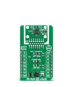
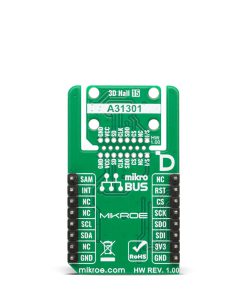
3D Hall 15 Click – I2C is a compact add-on board designed for precise 3D magnetic field measurement and angle calculation. It is based on the A31301EEJASR-XYZ-IC-06 3D linear Hall-effect sensor IC from Allegro Microsystems. The A31301 measures magnetic flux density across one, two, or all three axes with a range of ±600G and sensitivity of 26.8LSB/G, while supporting angle calculation in user-defined planes. It features both I2C (up to 1MHz) and optional SPI (up to 10MHz) interfaces, selected via configurable COMM SEL jumpers. The board also includes INT/SAMPLE jumper selection for interrupt or sample trigger functions, along with support for MIKROE’s Click Snap feature for flexible integration. This Click board is ideal for motor control feedback, camera gimbals, gamepad joysticks, robotic positioning, autonomous vehicles, and industrial motor control systems.
3D Hall 15 Click – I2C is fully compatible with the mikroBUS™ socket and can be used on any host system supporting the mikroBUS™ standard. It comes with the mikroSDK open-source libraries, offering unparalleled flexibility for evaluation and customization. What sets this Click board™ apart is the groundbreaking ClickID feature, enabling your host system to automatically detect and identify this add-on board, alongside a Click Snap feature introducing a new level of flexibility and ease of use.
NOTE: 3D Hall 15 Click – I2C comes equipped with the A31301EEJASR-XYZ-IC-06 sensor IC from Allegro Microsystems, preconfigured for I2C communication. If you are interested in the SPI-compatible version of this sensor, please contact our sales team for availability.
Stock: Lead-time applicable.
| 5+ | R209.00 |
| 10+ | R198.00 |
| 15+ | R187.00 |
| 20+ | R179.96 |
How does it work?
3D Hall 15 Click – I2C is based on the A31301EEJASR-XYZ-IC-06, a 3D linear Hall-effect sensor IC from Allegro Microsystems, that provides highly precise magnetic field measurements in three dimensions for a variety of embedded applications. It offers advanced low-power management and flexible magnetic sensing capabilities. This A31301 IC is capable of measuring applied flux density across any one, two, or all three axes simultaneously, while also supporting angle calculation in up to any two user-defined planes, making it highly versatile for complex magnetic sensing tasks. It features a standard magnetic field range of ±600G combined with a sensitivity of 26.8LSB/G, enabling precise detection of magnetic field variations.
.jpg)
Communication of the A31301EEJASR-XYZ-IC-06 with the host MCU is achieved via an I2C interface that supports operation up to 1MHz, and the device’s I2C address is programmable via EEPROM, allowing up to 127 unique addresses for multi-device configurations on the same I2C bus. Additionally, the A31301 includes a customer-programmable magnetic temperature coefficient with factory default trimming optimized for neodymium magnets, ensuring stable performance across varying temperatures.
The power management system of the A31301 is highly configurable, providing system-level flexibility to balance supply current consumption with sensor performance as needed. Its low-leakage sleep current mode makes it particularly well-suited for battery-powered and portable designs, including camera gimbals, gamepad joysticks, motor control feedback systems, RC autonomous vehicles, robotic position sensing solutions, and industrial motor control applications.
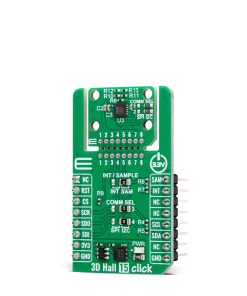
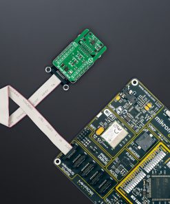
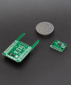
This Click board™ is designed in a unique format supporting the newly introduced MIKROE feature called “Click Snap.” Unlike the standardized version of Click boards, this feature allows the main IC area to become movable by breaking the PCB, opening up many new possibilities for implementation. Thanks to the Snap feature, the A31301EEJASR-XYZ-IC-06 can operate autonomously by accessing its signals directly on the pins marked 1-8. Additionally, the Snap part includes a specified and fixed screw hole position, enabling users to secure the Snap board in their desired location.
In addition to supporting the A31301EEJASR-XYZ-IC-06 variant, the 3D Hall 15 Click has been designed with a flexible footprint that accommodates other versions of the A31301 sensor family as well, including those that uses the SPI communication interface. The SPI-compatible variants offer high-speed communication capabilities, operating at clock frequencies up to 10MHz, providing an alternative for applications that require faster data transfer or prefer the deterministic nature of SPI over I2C. To support both communication protocols, the Click incorporates a set of COMM SEL jumpers that allow the user to select the desired interface by configuring all jumpers accordingly. It is important to emphasize that all COMM SEL jumpers must be set to the same position to ensure proper operation of the Click board, as mixed jumper settings may lead to communication errors or malfunction.
In addition to the primary communication pins, the 3D Hall 15 Click – I2C also uses two auxiliary pins labeled SAM and INT, which are dedicated to the sensor’s sample trigger and interrupt functions. Since both of these signals are multiplexed on a single multifunctional pin of the A31301 sensor, the board integrates an INT / SAMPLE jumper to conveniently select the desired operational mode. By setting this jumper accordingly, the user can easily configure the sensor’s pin behavior, either to output an interrupt signal or to serve as an external sample trigger input, depending on the application requirements.
This Click board™ can be operated only with a 3.3V logic voltage level. The board must perform appropriate logic voltage level conversion before using MCUs with different logic levels. It also comes equipped with a library containing functions and example code that can be used as a reference for further development.
Click Snap
Click Snap is an innovative feature of our standardized Click add-on boards, designed to bring greater flexibility and optimize your prototypes. By simply snapping the PCB along predefined lines, you can easily detach the main sensor/IC/module area, reducing the overall size, weight, and power consumption – ideal for the final phase of prototyping. For more details about Click Snap, visit the official page dedicated to this feature.
Specifications
Type
Magnetic
Applications
Ideal for motor control feedback, camera gimbals, gamepad joysticks, robotic positioning, autonomous vehicles, and industrial motor control systems
On-board modules
A31301EEJASR-XYZ-IC-06 – 3D linear Hall-effect sensor IC from Allegro Microsystems
Key Features
3D linear Hall-effect sensing, support for magnetic field measurements on one, two, or all three axes, angle calculation in user-defined planes, I2C communication up to 1MHz, programmable I2C address via EEPROM, customer-programmable magnetic temperature coefficient, support for MIKROE’s Click Snap mechanical integration, selectable interrupt or sample trigger function, and more
Interface
I2C
Feature
Click Snap,ClickID
Compatibility
mikroBUS™
Click board size
M (42.9 x 25.4 mm)
Input Voltage
3.3V
Pinout diagram
This table shows how the pinout on 3D Hall 15 Click – I2C corresponds to the pinout on the mikroBUS™ socket (the latter shown in the two middle columns).
| Notes | Pin | Pin | Notes | ||||
|---|---|---|---|---|---|---|---|
| NC | 1 | AN | PWM | 16 | SAM | Sample Trigger | |
| ID SEL | RST | 2 | RST | INT | 15 | INT | Interrupt |
| ID COMM | CS | 3 | CS | RX | 14 | NC | |
| NC | 4 | SCK | TX | 13 | NC | ||
| NC | 5 | MISO | SCL | 12 | SCL | I2C Clock | |
| NC | 6 | MOSI | SDA | 11 | SDA | I2C Data | |
| Power Supply | 3.3V | 7 | 3.3V | 5V | 10 | NC | |
| Ground | GND | 8 | GND | GND | 9 | GND | Ground |
Onboard settings and indicators
| Label | Name | Default | Description |
|---|---|---|---|
| LD1 | PWR | – | Power LED Indicator |
| JP1-JP2 | COMM SEL | Right | Snap Communication Interface Selection SPI/I2C: Left position SPI, Right position I2C (factory configuration only) |
| JP3 | INT / SAMPLE | Right | Interrupt / Sample Trigger Selection INT/SAM: Left position INT, Right position SAM |
| JP4-JP5 | COMM SEL | Right | Communication Interface Selection SPI/I2C: Left position SPI, Right position I2C (factory configuration only) |
3D Hall 15 Click – I2C electrical specifications
| Description | Min | Typ | Max | Unit |
|---|---|---|---|---|
| Supply Voltage | – | 3.3 | – | V |
| Magnetic Field Range | -600 | – | +600 | G |
| Sensitivity | – | 26.8 | – | LSB/G |
Software Support
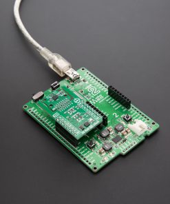
3D Hall 15 Click – I2C demo application is developed using the NECTO Studio, ensuring compatibility with mikroSDK‘s open-source libraries and tools. Designed for plug-and-play implementation and testing, the demo is fully compatible with all development, starter, and mikromedia boards featuring a mikroBUS™ socket.
Example Description
This example demonstrates the use of 3D Hall 15 Click – I2C by reading the magnetic flux density from 3 axes, and the angle and magnitude between X and Y axes
as well as the sensor internal temperature.
Key Functions
c3dhall15i2c_cfg_setupThis function initializes Click configuration structure to initial values.c3dhall15i2c_initThis function initializes all necessary pins and peripherals used for this Click board.c3dhall15i2c_default_cfgThis function executes a default configuration of 3D Hall 15 I2C Click board.c3dhall15i2c_read_dataThis function reads the temperature, X, Y, Z magnetic field, angle, and magnitude from the device.
Application Init
Initializes the driver and performs the Click default configuration.
Application Task
Reads data from the sensor approximately every 100ms and displays the measurement values on the USB UART.
Application Output
This Click board can be interfaced and monitored in two ways:
- Application Output – Use the “Application Output” window in Debug mode for real-time data monitoring. Set it up properly by following this tutorial.
- UART Terminal – Monitor data via the UART Terminal using a USB to UART converter. For detailed instructions, check out this tutorial.
Additional Notes and Information
The complete application code and a ready-to-use project are available through the NECTO Studio Package Manager for direct installation in the NECTO Studio. The application code can also be found on the MIKROE GitHub account.
Resources
Downloads
| Weight | 17 g |
|---|---|
| Brand | MikroElektronika |