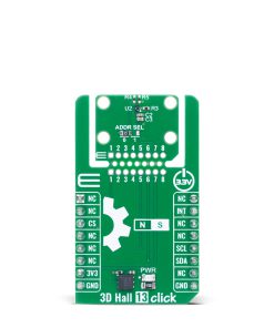
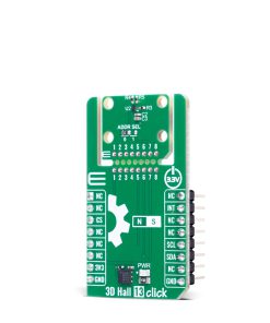
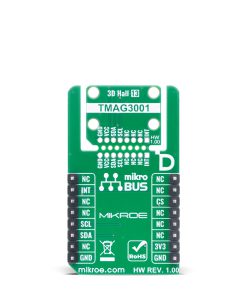
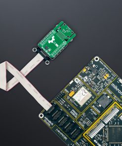
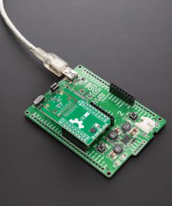
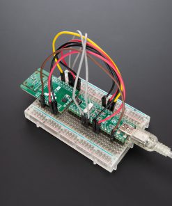
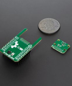
3D Hall 13 Click is a compact add-on board designed for contactless 3D magnetic field sensing and precise angular position measurements. It is based on the TMAG3001, a low-power 3D linear Hall-effect and angle sensor from Texas Instruments with integrated CORDIC engine and 12-bit ADC. This Click board™ supports I2C communication up to 1MHz and features three-axis magnetic sensing with a ±75mT range and high sensitivity of 885LSB/mT, along with configurable magnetic axes, temperature sensing, and low-power modes including sleep and wake-up. It introduces the unique “Click Snap” feature, allowing the sensor area to be detached and mounted separately for flexible integration. 3D Hall 13 Click is perfectly suited for applications such as smart locks, proximity sensors, robotics motor control, wearable gesture detection, and gaming controller input systems.
3D Hall 13 Click is fully compatible with the mikroBUS™ socket and can be used on any host system supporting the mikroBUS™ standard. It comes with the mikroSDK open-source libraries, offering unparalleled flexibility for evaluation and customization. What sets this Click board™ apart is the groundbreaking ClickID feature, enabling your host system to automatically detect and identify this add-on board, alongside a Click Snap feature introducing a new level of flexibility and ease of use.
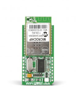 WiFi Plus Click
1 × R2,150.00
WiFi Plus Click
1 × R2,150.00 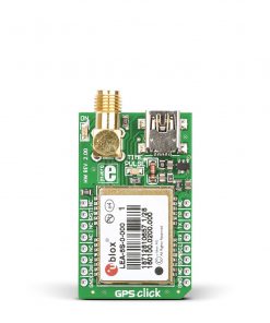 GPS Click
1 × R1,050.00
GPS Click
1 × R1,050.00 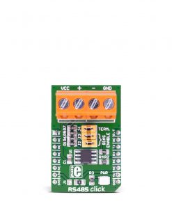 RS485 Click 5V
1 × R225.00
RS485 Click 5V
1 × R225.00  EXPAND Click
2 × R250.00
EXPAND Click
2 × R250.00 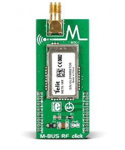 M-BUS RF click
1 × R940.00
M-BUS RF click
1 × R940.00