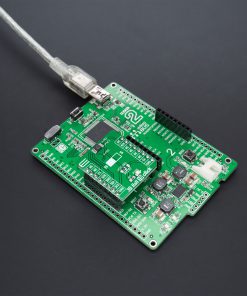
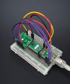
How does it work?
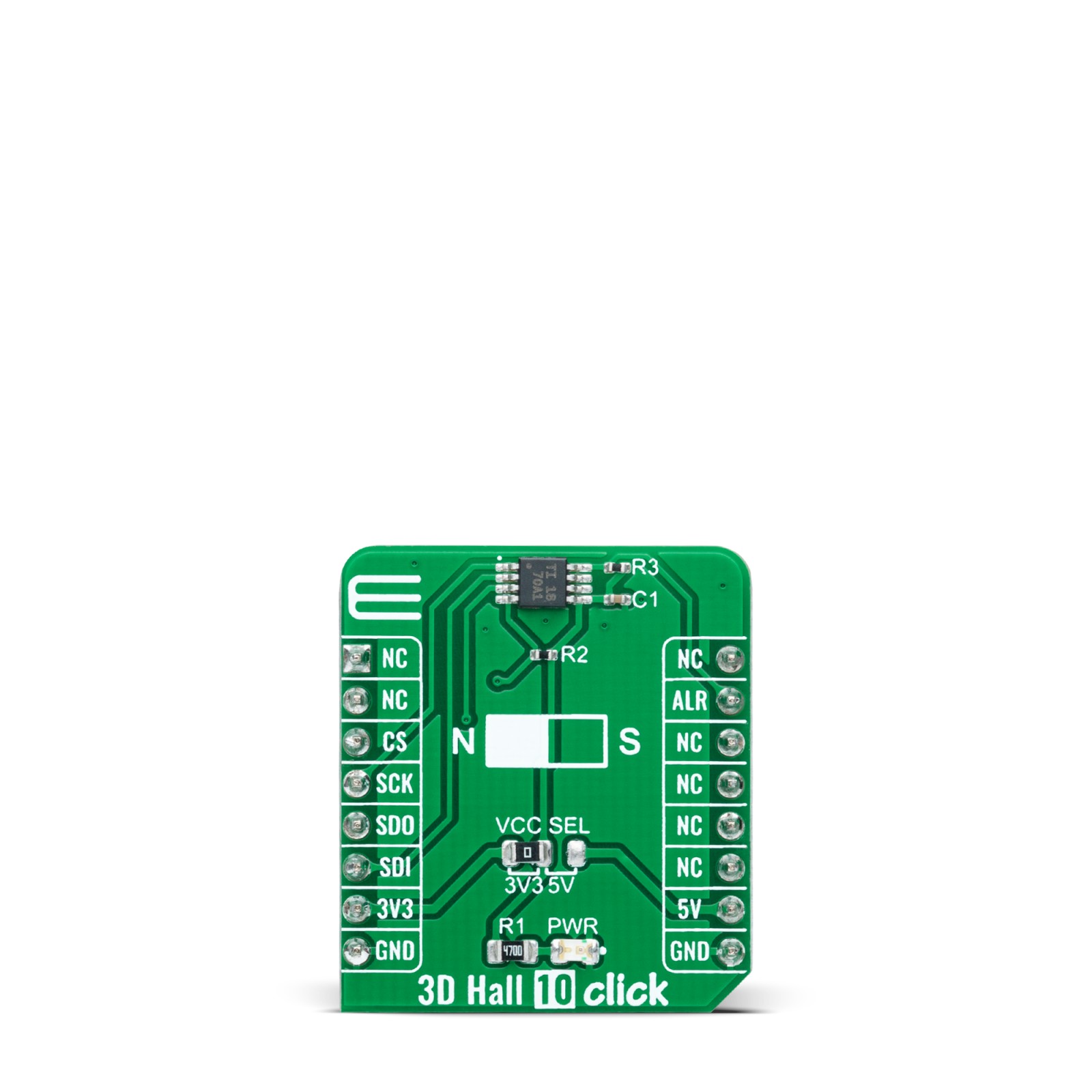
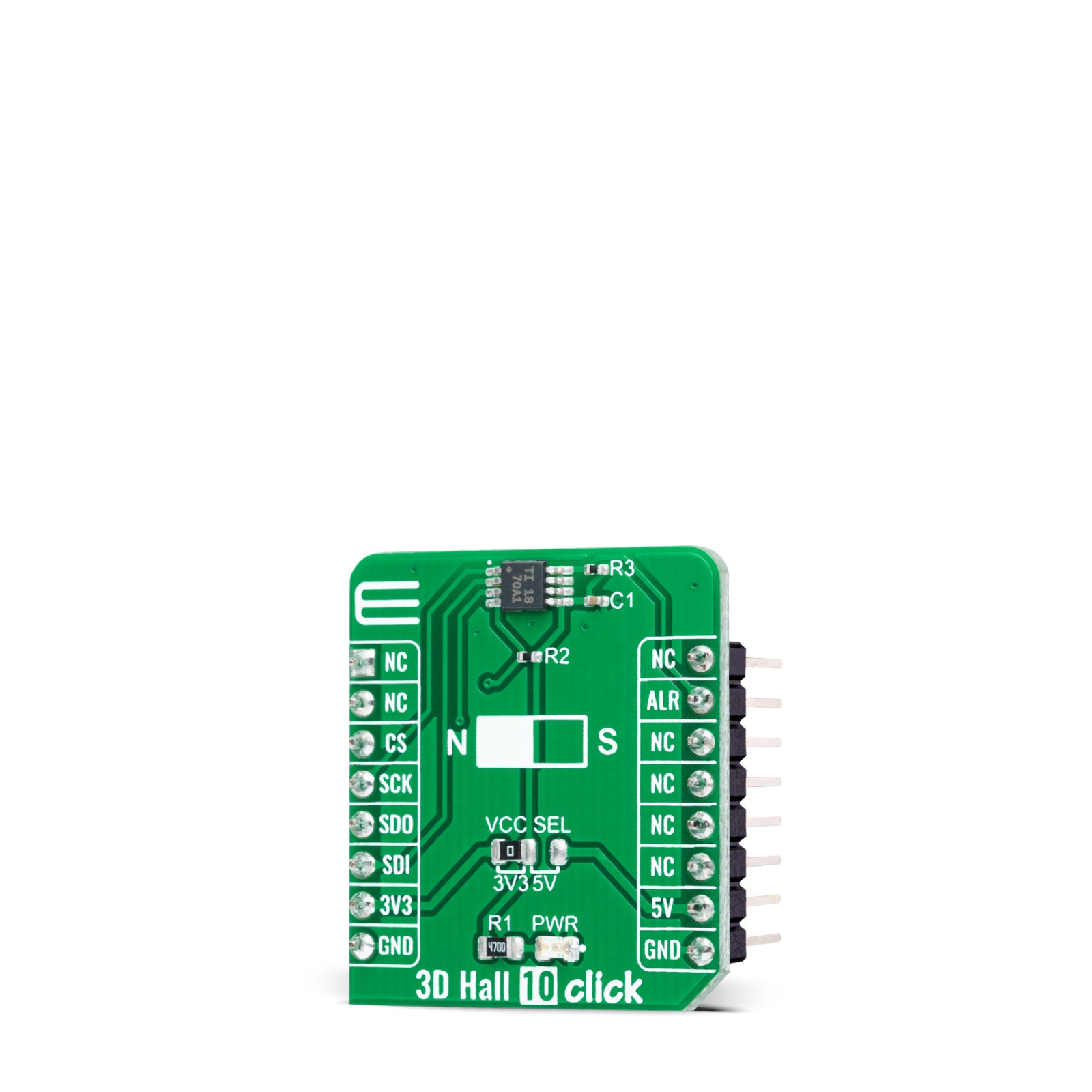
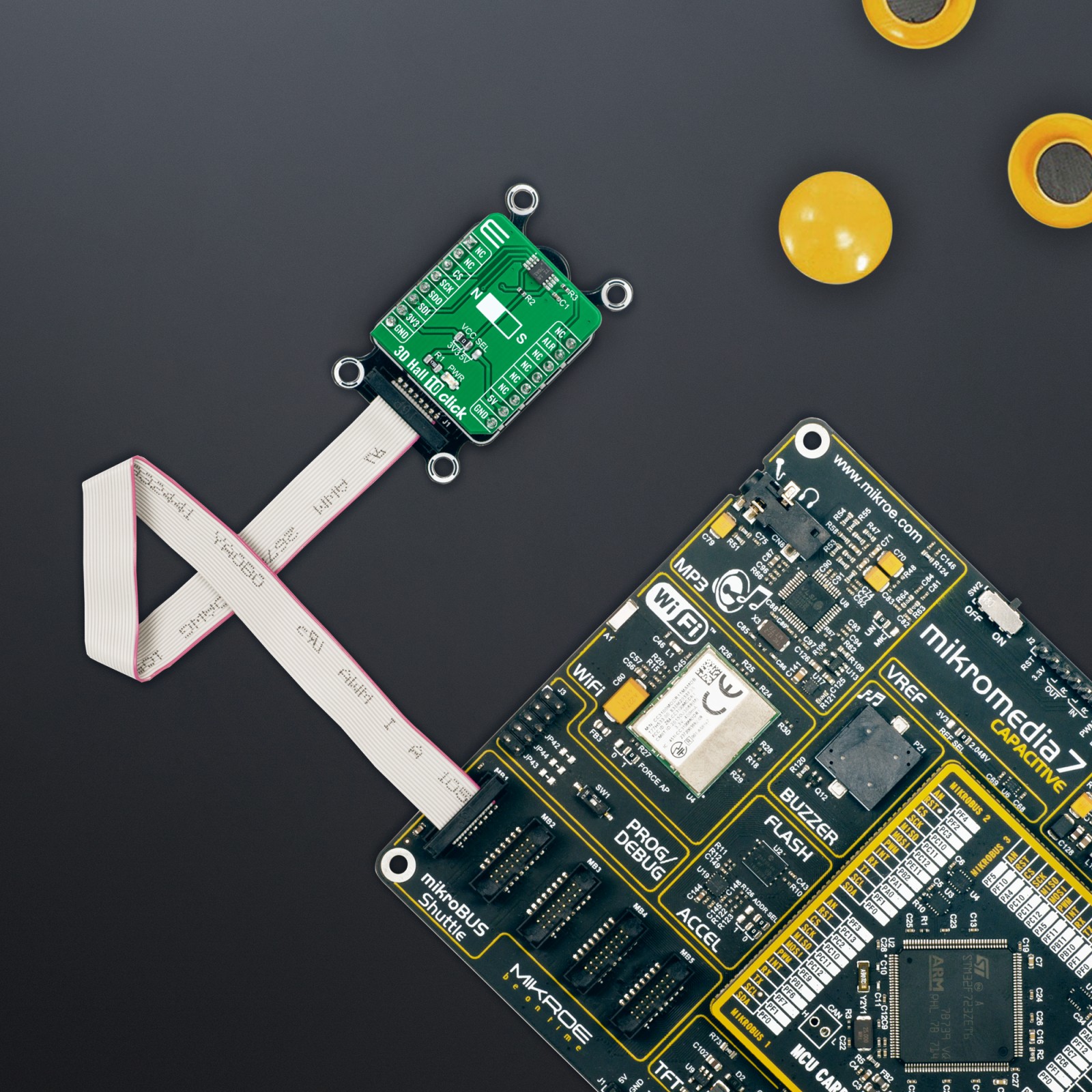
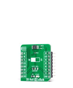
3D Hall 10 Click as its foundation uses the TMAG5170, a 3D linear Hall-effect sensor used to detect the strength of a magnetic field in all three dimensions (X, Y, and Z axes) in a range from ±25mT to ±100mT from Texas Instruments. The high level of integration offers flexibility and accuracy in various industrial and personal electronics applications such as position sensing systems. A precision signal chain and an integrated 12-bit ADC enable high accuracy and low drift magnetic field measurements while supporting a sampling of up to 20ksps.
An integrated angle calculation engine (CORDIC) is performed using two user-selected magnetic axes and provides complete 360° angular position information for both on- and off-axis angle measurement topologies. The device also features magnetic gain and offset correction to mitigate the impact of system mechanical error sources.
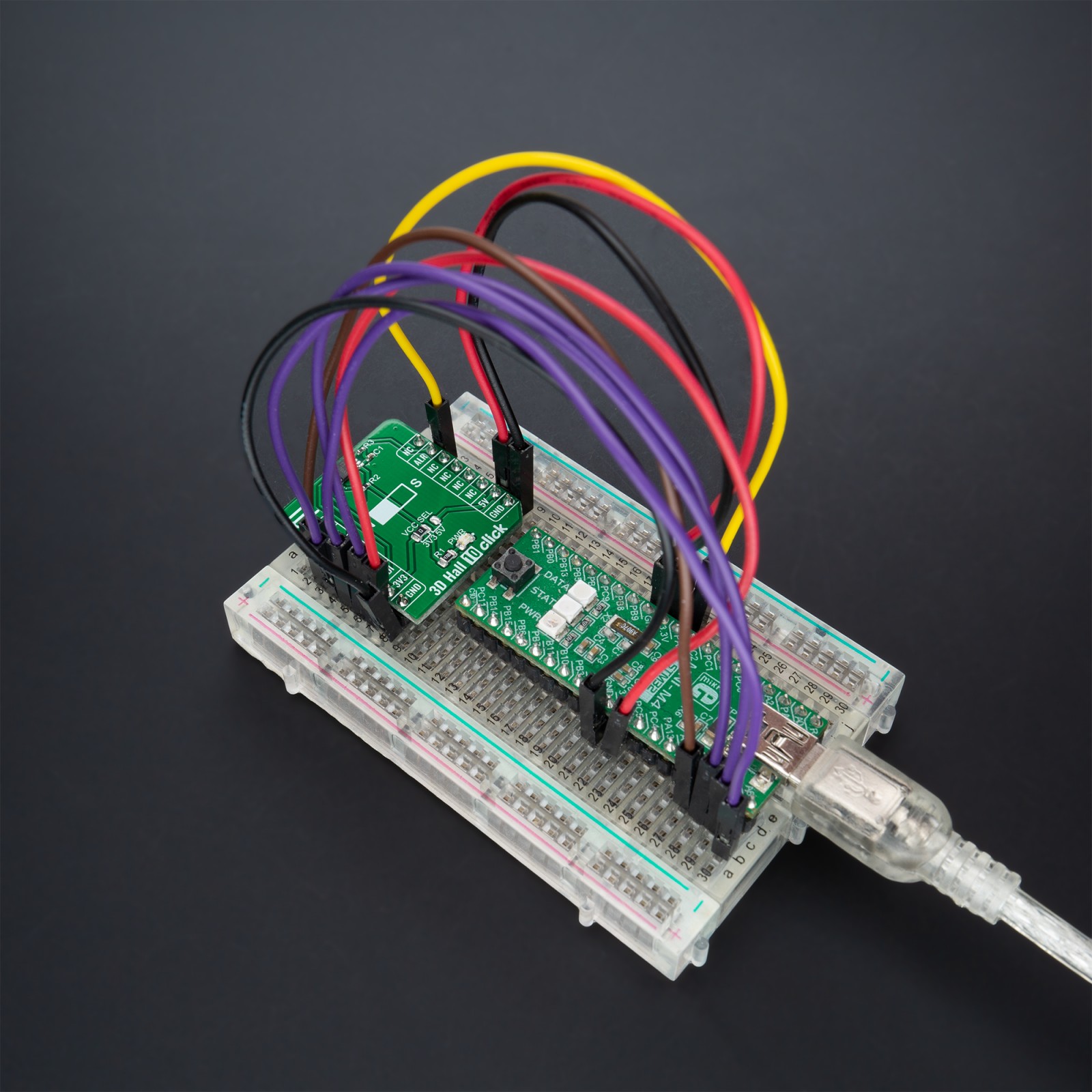
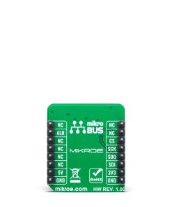
3D Hall 10 Click communicates with MCU through a register-selectable standard SPI interface that enables high clock speed up to 10MHz to enable any combination of magnetic axes and temperature measurements. The SPI communication features a user-enabled cyclic redundancy check to enhance the data integrity. A dedicated alert pin marked as ALR and routed on the INT pin of the mikroBUS™ socket can act as a system interrupt during low power Wake-up and Sleep mode and be used by an MCU to trigger a new sensor conversion. Besides, the TMAG5170 offers multiple diagnostics features to detect and report both system and device-level failures.
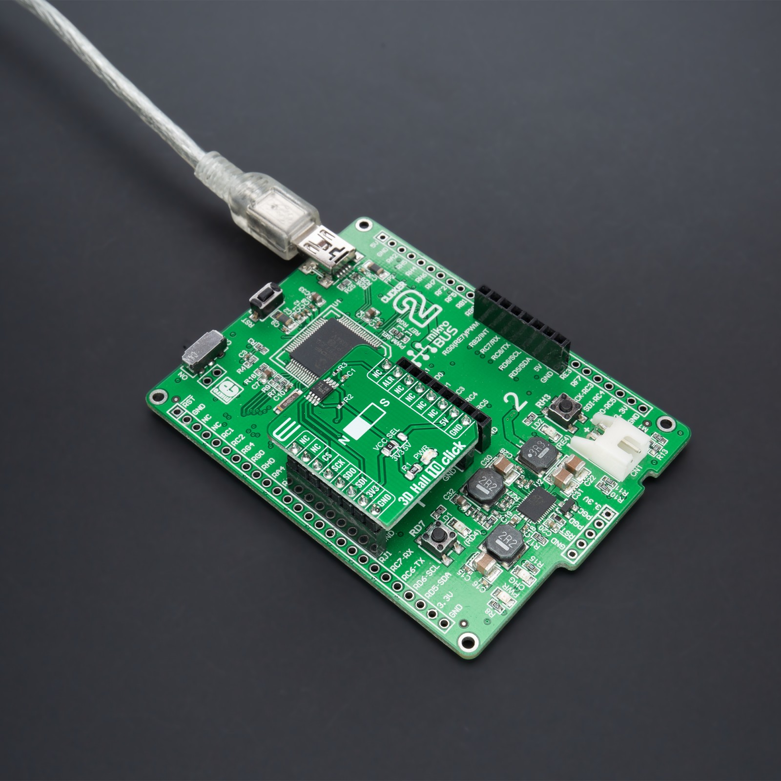
This Click board™ can operate with both 3.3V and 5V logic voltage levels selected via the VCC SEL jumper. This way, it is allowed for both 3.3V and 5V capable MCUs to use the communication lines properly. However, the Click board™ comes equipped with a library containing easy-to-use functions and an example code that can be used, as a reference, for further development.
Specifications
Type
Magnetic
Applications
Can be used for a wide range of industrial and personal electronics applications such as automation, motor-drive applications, and more
On-board modules
TMAG5170 – linear 3D Hall effect sensor from Texas Instruments
Key Features
High precision, optimizes position sensing speed and accuracy, autonomous wake-up and sleep mode, alert feature, integrated diagnostics for fault detection, integrated angle CORDIC calculation with gain and offset adjustment, low power consumption, and more
Interface
SPI
Compatibility
mikroBUS
Click board size
S (28.6 x 25.4 mm)
Input Voltage
3.3V or 5V
Pinout diagram
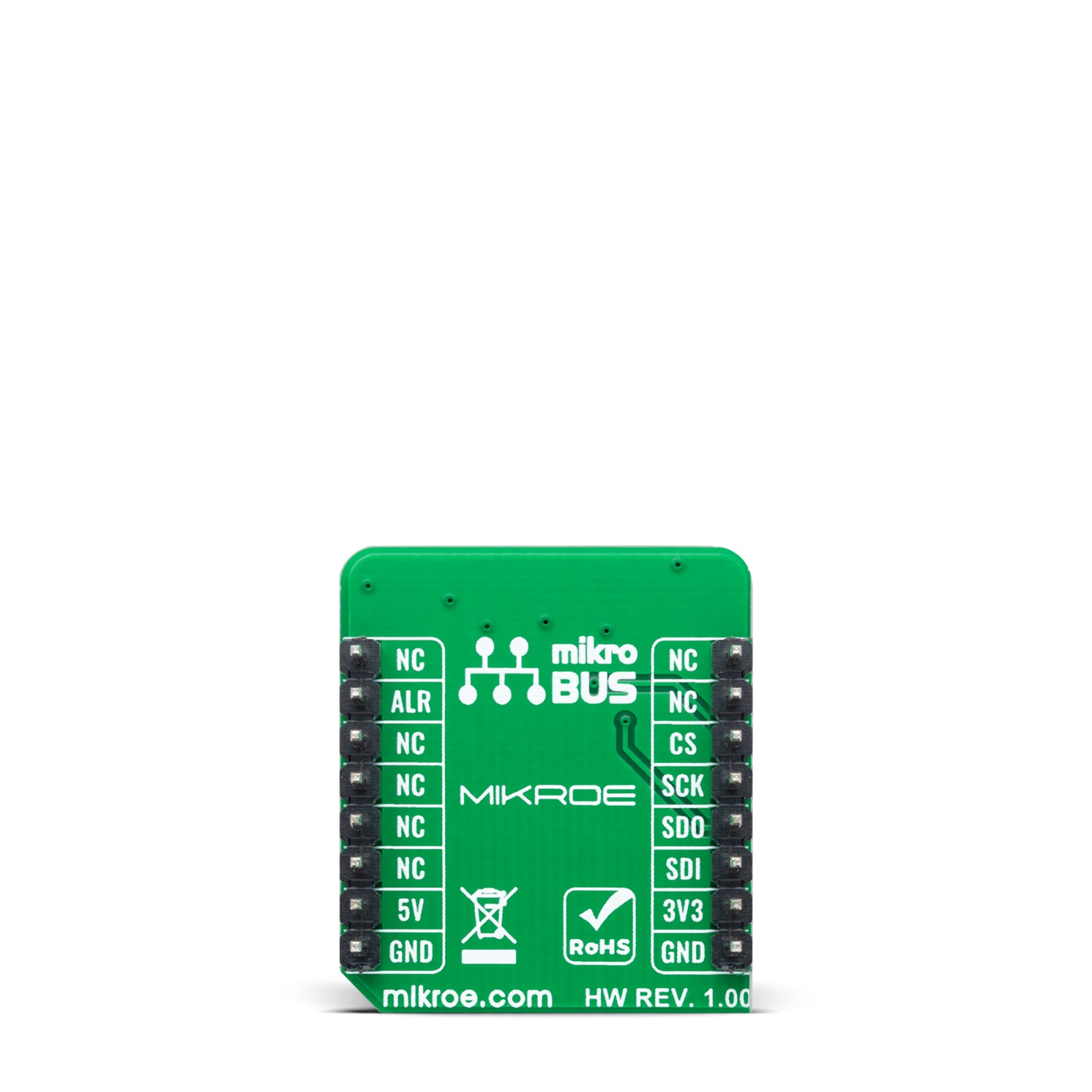
This table shows how the pinout on 3D Hall 10 Click corresponds to the pinout on the mikroBUS™ socket (the latter shown in the two middle columns).
Onboard settings and indicators
Label | Name | Default | Description |
---|---|---|---|
LD1 | PWR | – | Power LED Indicator |
JP1 | VCC SEL | Left | Logic Level Voltage Selection 3V3/5V: Left position 3V3, Right position 5V |
3D Hall 10 Click electrical specifications
Description | Min | Typ | Max | Unit |
---|---|---|---|---|
Supply Voltage | 3.3 | – | 5 | V |
Operating Magnetic Range | ±25 | – | ±100 | mT |
Sample Rate | – | – | 20 | ksps |
Resolution | – | 12 | – | bit |
Operating Temperature Range | -40 | +25 | 120 | °C |
Software Support
We provide a library for the 3D Hall 10 Click as well as a demo application (example), developed using MikroElektronika compilers. The demo can run on all the main MikroElektronika development boards.
Package can be downloaded/installed directly from NECTO Studio Package Manager(recommended way), downloaded from our LibStock™ or found on Mikroe github account.
Library Description
This library contains API for 3D Hall 10 Click driver.
Key functions
-
c3dhall10_get_alert_pin
This function returns the alert (ALR) pin logic state. The alert pin is configured as a conversion complete interrupt by default. -
c3dhall10_read_data
This function reads new data which consists of X, Y, and Z axis values in mT, and temperature in Celsius. It also reads the angle in Degrees between X and Y by default, and magnitude data as well. -
c3dhall10_write_frame
This function writes a desired data to the selected register by using SPI serial interface.
Example Description
This example demonstrates the use of 3D Hall 10 Click board™ by reading the magnetic flux density from 3 axes, and the angle and magnitude between X and Y axes as well as the sensor internal temperature.
void application_task ( void )
{
while ( c3dhall10_get_alert_pin ( &c3dhall10 ) );
c3dhall10_data_t sensor_data;
if ( C3DHALL10_OK == c3dhall10_read_data ( &c3dhall10, &sensor_data ) )
{
log_printf( &logger, " X-axis: %.1f mTrn", sensor_data.x_axis );
log_printf( &logger, " Y-axis: %.1f mTrn", sensor_data.y_axis );
log_printf( &logger, " Z-axis: %.1f mTrn", sensor_data.z_axis );
log_printf( &logger, " Angle: %.1f Degreesrn", sensor_data.angle );
log_printf( &logger, " Magnitude: %urn", sensor_data.magnitude );
log_printf( &logger, " Temperature: %.2f Celsiusrnn", sensor_data.temperature );
}
}
The full application code, and ready to use projects can be installed directly from NECTO Studio Package Manager(recommended way), downloaded from our LibStock™ or found on Mikroe github account.
Other Mikroe Libraries used in the example:
- MikroSDK.Board
- MikroSDK.Log
- Click.3DHall10
Additional notes and informations
Depending on the development board you are using, you may need USB UART click, USB UART 2 Click or RS232 Click to connect to your PC, for development systems with no UART to USB interface available on the board. UART terminal is available in all MikroElektronika compilers.
mikroSDK
This Click board™ is supported with mikroSDK – MikroElektronika Software Development Kit. To ensure proper operation of mikroSDK compliant Click board™ demo applications, mikroSDK should be downloaded from the LibStock and installed for the compiler you are using.
For more information about mikroSDK, visit the official page.