16×9 G Click
R715.00 ex. VAT
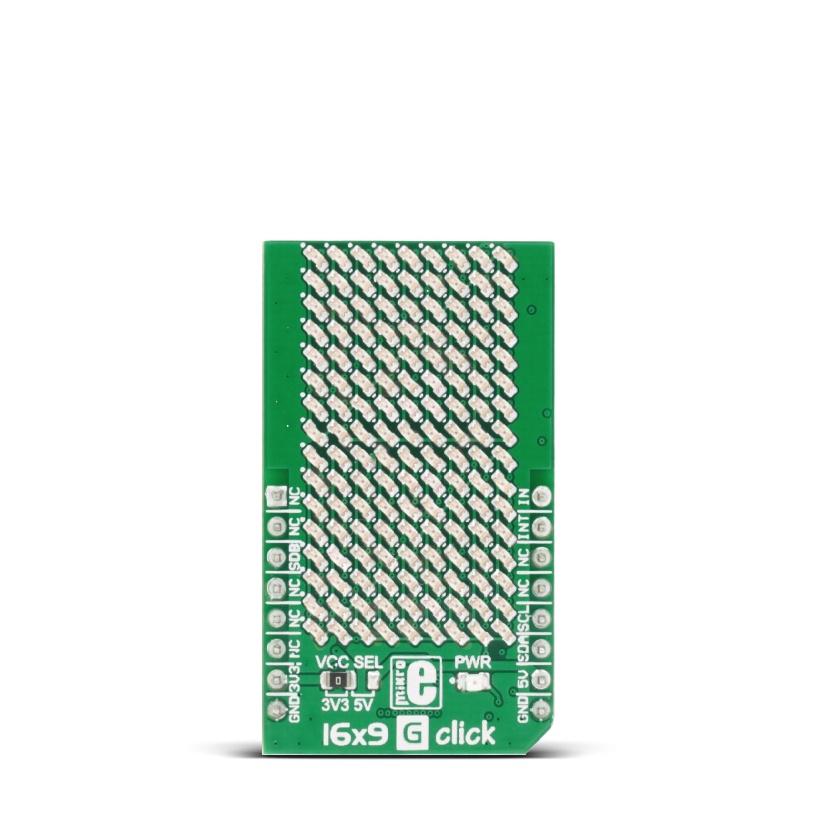
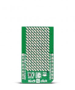
16×9 click is an array of 144 LEDs, driven by a single IC with relatively low pin count (28). Driving so many LED elements with reasonably low pin count IC is possible by utilizing a cross-plexing LED driving technique. This technique is also known as the Charlie-plexing since it was first proposed by Charlie Allen, an engineer from Maxim Integrated. The technique does not allow all LEDs independently to be controlled, however by employing the persistence of vision phenomenon, it is possible to trick eyes that all LED elements can actually be controlled independently.
Stock: Lead-time applicable.
| 5+ | R679.25 |
| 10+ | R643.50 |
| 15+ | R607.75 |
| 20+ | R584.87 |
16×9 click utilizes the IS31FL3731, a LED array driver from Integrated Silicon Solution, Inc, which employs the cross-plexing technique to drive up to 144 LEDs. It drives LED array with constant current set by a single resistor, can store up to 8 frames in its memory making it able to play short animations, it has two separate modes optimized for displaying animation or pictures, it has 256 steps of brightness for each LED, can use various breathing or blinking effects between frames, can even use audio signal to modulate the intensity or advance the playback, and it uses the fast I2C interface for the communication. The chip also offers INT and STB lines (interrupt and stand-by), allowing simple control by the host MCU. This IC requires a very low count of additional components, which simplifies the design. It can be used in entertainment or gaming industry, for development of various types of LED display applications, and similar.
How does it work?
The main device on the 16×9 click is the IS31FL3731, a LED array driver from ISSI. This device uses the cross-plexing technology which allows it to drive a large number of LED segments (144) with a small number of I/O pins. The IC has 28 pins in total, but it has two matrices with only 9 pins each for LED driving – which makes it 18 pins in total. It is possible by using the cross-plexing technique, also known as the Charlie-plexing, named by Charlie Allen, an engineer from Maxim Integrated, who made the first practical application example by utilizing this technique, for the company he was working at. The working principle of this technique is based around using Hi-Z pins. This adds the third element for the LED control, unlike the commonly used matrix multiplexing, when two pins can change states to either LOW-HI or HI-LOW, saving only a single pin per cell. A basic cell of the cross-plexed LED matrix consists of three pins and 6 LEDs which is substantially more than the regular matrix. The bigger the matrix is, the higher the efficiency of such multiplexing becomes. N pins are able to drive N2-N LED segments.

The IS31FL3731 has some additional features. Besides two banks of driving pins, it can store up to 8 frames in its internal memory. This allows small movies to be autonomously played back by the IC itself, without using the MCU processing power. The device can operate in Picture Mode, in the Auto Frame Mode, and in the Audio Frame Mode. While operating in Picture mode, it will display a selected frame and can apply a breathing effect to it. Auto Frame Mode will sequence through all the frames. The delay between frames, as well as the transition effect, can be configured by the user. The Auto Frame Mode can also be used as the buffer for playing back more frames, which can be externally loaded to the IC while it plays back its 8 frames buffer. Finally, the Audio Frame Mode allows the audio signal at the IN pin to control the frame rate advancement (lowest signal level will display the first frame, the highest signal level will display the last frame). All the programmable parameters are stored via the I2C to appropriate registers. The datasheet of the IS31FL3731 offers ian n-depth explanation of all the registers.
The interrupt engine allows the interrupt event to be generated by pulling the INTB pin to a LOW logic level and setting the appropriate status register bit to 1. INTB pin will report whenever the cycle in the Auto Frame Mode is finished. Every time when the frame sequence is ended, this pin will be pulsed to a LOW logic level, and after 7ms, it will return to a HIGH logic level, automatically. The INT bit signalizing the interrupt will be cleared once the Status Register is read by the host MCU but will not automatically revert to 0. The INTB pin is routed to the mikroBUS™ INT pin.
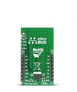
The SDB pin can be used to completely turn off the IC when power saving is a concern. Pulling this pin to a LOW logic level will put the device into the Hardware Shutdown Mode, which powers down the entire IC. No read or write operations are possible, unlike the Software Shutdown Mode, which is set by a bit in the respective (Shutdown) register. Software shutdown Mode will turn off the drivers and most of the IC, but the communication will be possible. In fact, some registers can be read only in Software Shutdown Mode, such as the Frame registers. The SDB pin is normally pulled to a LOW logic level by the onboard pulldown resistor, so initialization procedure should contain setting this pin to a HIGH logic level. The SDB pin routed to the mikroBUS™ CS pin and it is labeled as SDB.
The IN pin of the IS31FL3731 is used to sample the input data and either modulate the LED segment brightness according or advance the playback frame. It is decoupled by a capacitor, accepting the line-level audio signal. On the 16×9 Click board™, this pin is routed to the PWM pin of the mikroBUS™, thus the PWM signal from the MCU can be used instead of the audio signal. Naturally, the device will still react to an audio source, since the PWM signal is just another type of a waveform applied to the IN pin. The PWM pin of the mikroBUS™ is labeled as IN on the Click board™.
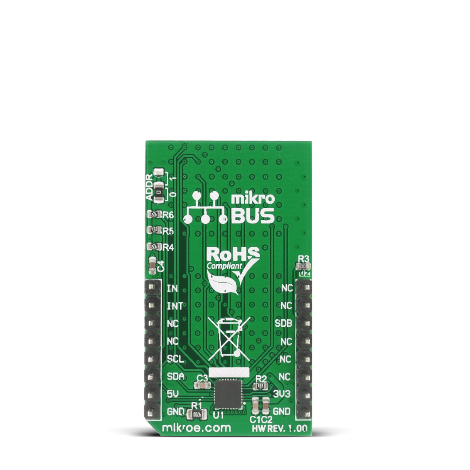
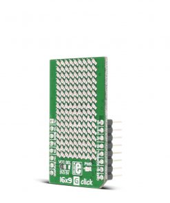
There are two SMD jumpers on this Click board™. The first SMD jumper is used to select the least significant bit (LSB) of the I2C address, and it is labeled as the ADDR SEL. The second SMD jumper is labeled as the VCC SEL and it is used to set the operating voltage of the device, allowing it to be interfaced with both 3.3V and 5V MCUs.
Specifications
Type
LED Matrix
Applications
It can be used in entertainment or gaming industry, for development of various types of LED display applications, and similar.
On-board modules
IS31FL3731, a matrix LED display driver, from Integrated Silicon Solution, Inc
Key Features
144 LED matrix display, memory for storing up to 8 frames, programmable transitions including breathing and blinking effects, audio/pwm modulation of the frame advancement or the LED segment intensity, low number of pins and external components, and more
Interface
I2C,PWM
Feature
No ClickID
Compatibility
mikroBUS™
Click board size
M (42.9 x 25.4 mm)
Input Voltage
3.3V or 5V
Pinout diagram
This table shows how the pinout on 16×9 G click corresponds to the pinout on the mikroBUS™ socket (the latter shown in the two middle columns).
Onboard Jumper and Settings
| Label | Name | Default | Description |
|---|---|---|---|
| PWR | PWR | – | Power LED indicator |
| VCC SEL | VCC SEL | Left | Operating voltage level selection: left position 3.3V, right position 5V |
| ADDR SEL | ADDR SEL | Down | I2C address LSB selection: up position 1, down position 0 |
Software support
We provide a library for the 16x9G Click on our LibStock page, as well as a demo application (example), developed using MikroElektronika compilers. The demo can run on all the main MikroElektronika development boards.
Library Description
The library initializes and defines the I2C bus driver that offers a choice for writing data in the register. The library includes a function for displaying one character, image, or rectangle drawing. The user also has the function for display refresh and control all LEDs.
Key functions:
void c16x9g_drawPoint(uint8_t x, uint8_t y, uint8_t pwm)– Functions for draw pointvoid c16x9g_displayByte(char ch, uint8_t frame, uint8_t pwm)– Function for displaying one charactervoid c16x9g_displayRefresh()– Function for refresh displayvoid c16x9g_displayImage(uint8_t *pImage, uint8_t frame, uint8_t pwm)– Image display function
Example description
The application is composed of three sections:
- System Initialization - Initializes I2C module
- Application Initialization - Initializes driver init
- Application Task – (code snippet) - Display character, image and rectangle every 1 second.
void applicationTask()
{
 c16x9g_displayRefresh();
 c16x9g_displayByte(demoChar, C16X9G_FRAME_1, 250);
 Delay_1sec();

 c16x9g_displayRefresh();
 c16x9g_displayImage(&demoImageOn[0], C16X9G_FRAME_1, 250);
 Delay_1sec();

 c16x9g_displayRefresh();
 c16x9g_displayImage(&demoImageOff[0], C16X9G_FRAME_1, 250);
 Delay_1sec();

 c16x9g_displayRefresh();
 c16x9g_drawRectangle(1,4,6,4,250);
 Delay_1sec();
}
The full application code, and ready to use projects can be found on our Libstock page.
Other MikroElektronika libraries used in the example:
- I2C
Additional notes and information
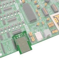
Depending on the development board you are using, you may need USB UART click, USB UART 2 click or RS232 click to connect to your PC, for development systems with no UART to USB interface available on the board. The terminal available in all MikroElektronika compilers, or any other terminal application of your choice, can be used to read the message.
mikroSDK
This click board is supported with mikroSDK - MikroElektronika Software Development Kit. To ensure proper operation of mikroSDK compliant click board demo applications, mikroSDK should be downloaded from the LibStock and installed for the compiler you are using.
For more information about mikroSDK, visit the official page.
Resources
Downloads
| Weight | 20 g |
|---|---|
| Brand | MikroElektronika |

