How does it work?
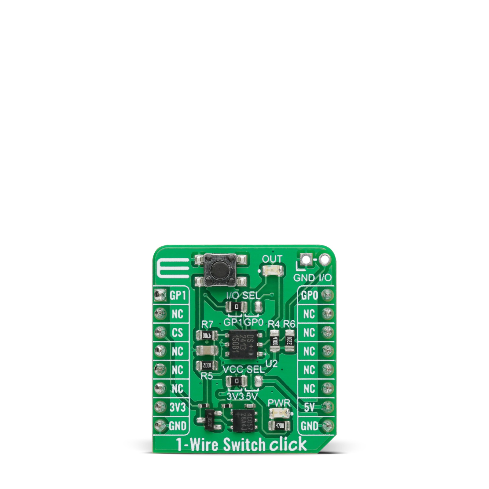
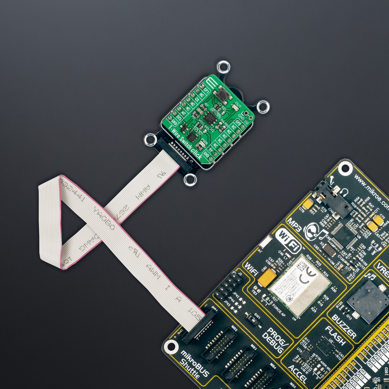
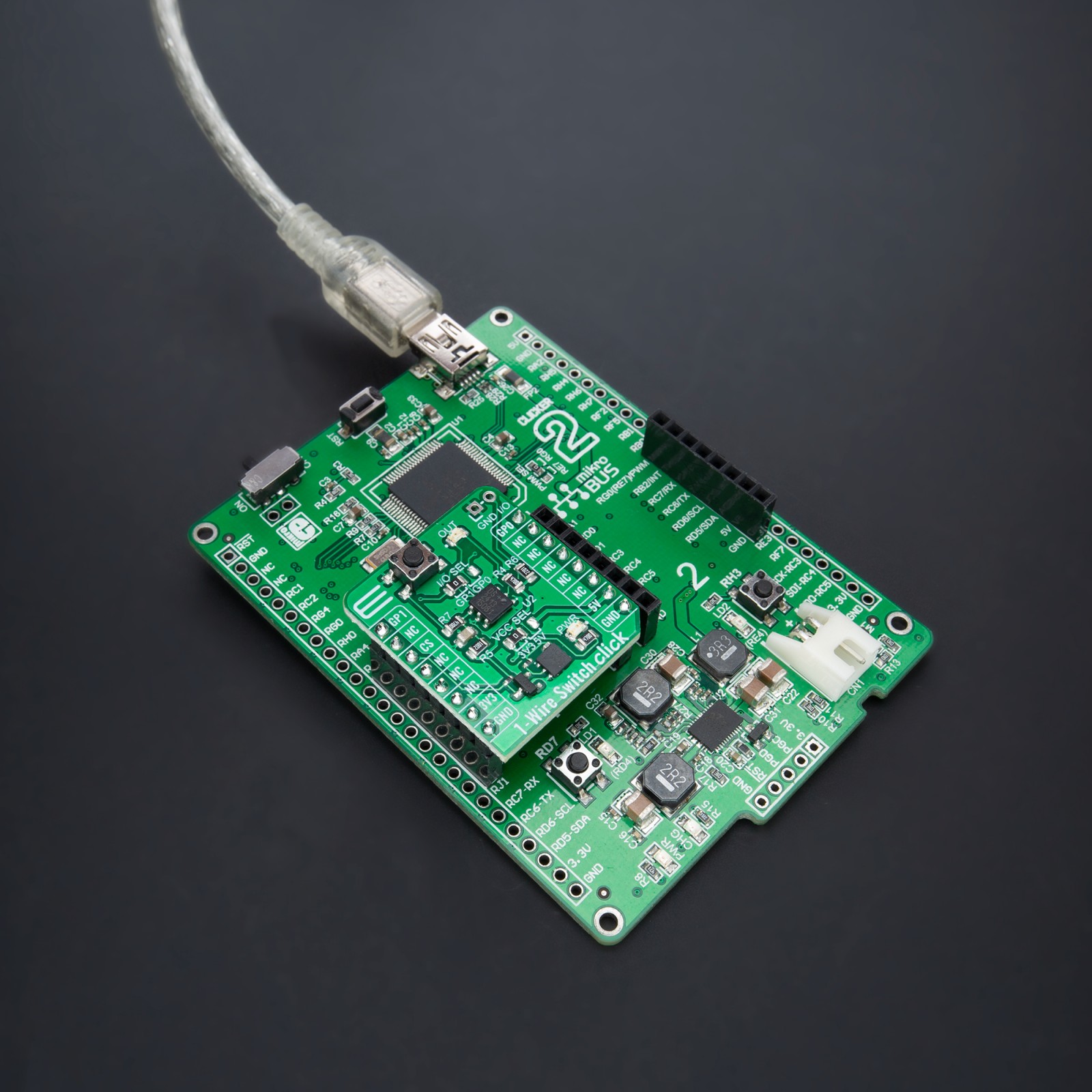
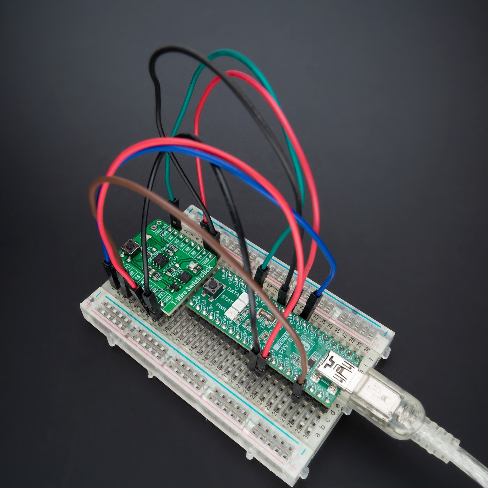
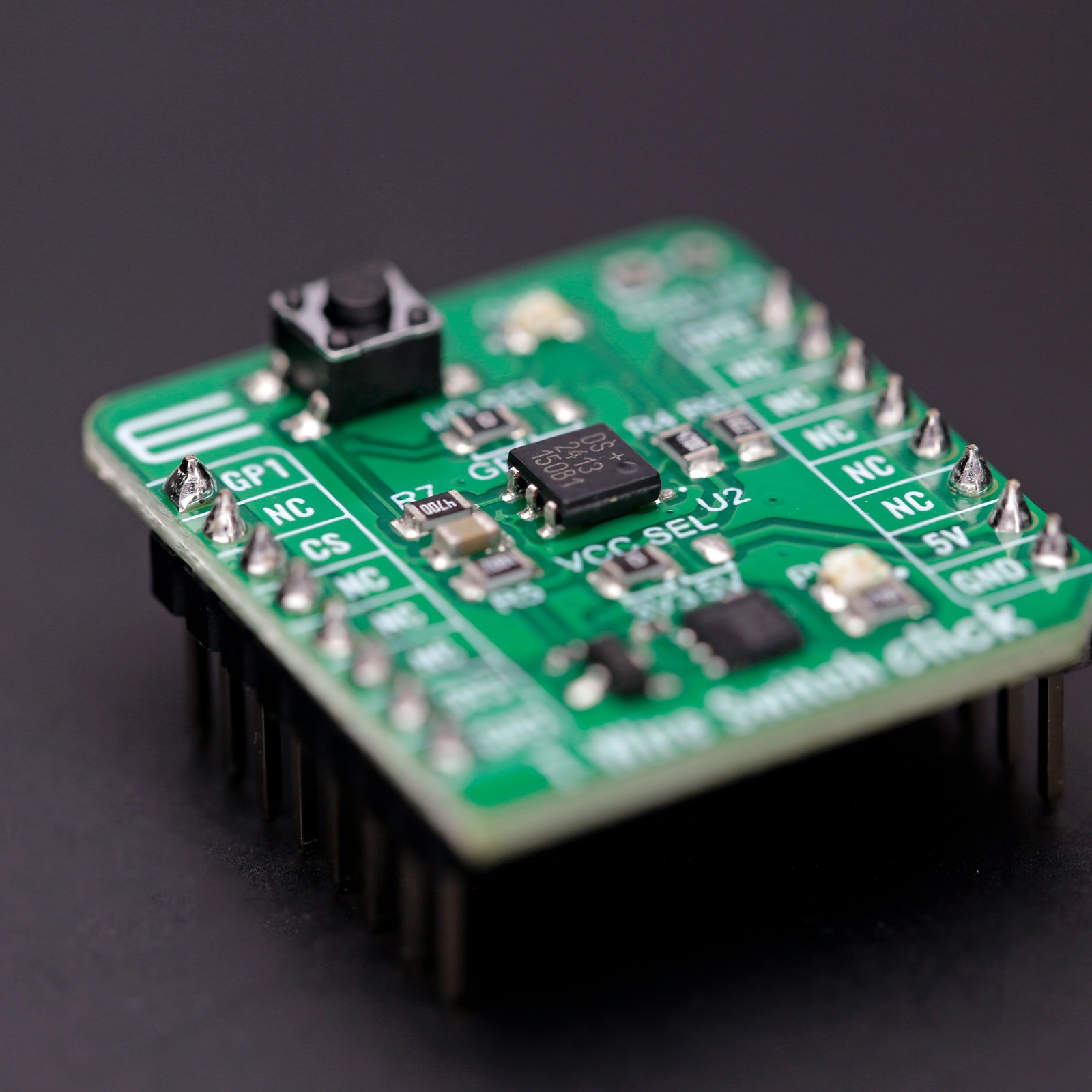
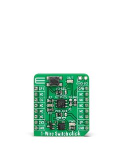
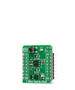
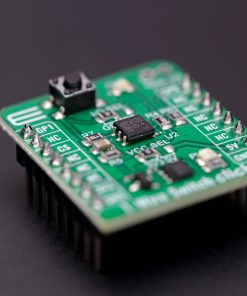
1-Wire Switch Click is based on the DS2413, a dual-channel addressable switch from Analog Devices. The DS2413 combines two programmable I/O pins and a fully featured 1-Wire interface in a single package, ensuring that PIO output changes occur error-free. The PIO outputs are configured as open-drain, operate at up to 28V (provide a high level of fault tolerance in the end application), and have an ON-resistance of 20Ω maximum. By monitoring the voltage at its programmable I/O pins, the DS2413 lets you read back the state of the load, in this case, the state of the button, which in this configuration is in the role of input, while the output state is visually detected through the red LED marked with OUT.
The DS2413’s power is supplied parasitically from the 1-Wire bus, a system with a single bus controller and one or more peripherals. With that in mind, this Click board™ has one additional unpopulated header, which enables the connection of other external 1-Wire devices, thus forming a line with several peripherals on one controller. The DS2413 also has a 64-bit long registration number that guarantees unique identification. This number addresses the device in a multidrop 1-Wire network environment, where multiple devices reside on a common 1-Wire bus and operate independently.
As mentioned, the 1-Wire Switch Click communicates with MCU using the 1-Wire interface that, by definition, requires only one data line (and ground) for communication with MCU. The 1-Wire communication line is routed to the SMD jumper labeled as I/O SEL, which allows routing of the 1-Wire communication either to the GP0 pin or the GP1 pin of the mikroBUS™ socket. These pins are labeled, respectively, the same as the SMD jumper positions, making the selection of the desired pin simple and straightforward.
This Click board™ can operate with either 3.3V or 5V logic voltage levels selected via the VCC SEL jumper. This way, both 3.3V and 5V capable MCUs can use the communication lines properly. However, the Click board™ comes equipped with a library containing easy-to-use functions and an example code that can be used, as a reference, for further development.
Specifications
Type
1-Wire
Applications
Can be used for industrial control, key-pick systems, accessory identification and control, and more
On-board modules
DS2413 – dual-channel 1-Wire switch from Analog Devices
Key Features
Configured as open-drain, parasitic power supply through 1-Wire, high performance, unique 64-bit ROM factory-lasered serial number, low power consumption, selectable communication pin, and more
Interface
1-Wire
Feature
ClickID
Compatibility
mikroBUS™
Click board size
S (28.6 x 25.4 mm)
Input Voltage
3.3V or 5V
Pinout diagram
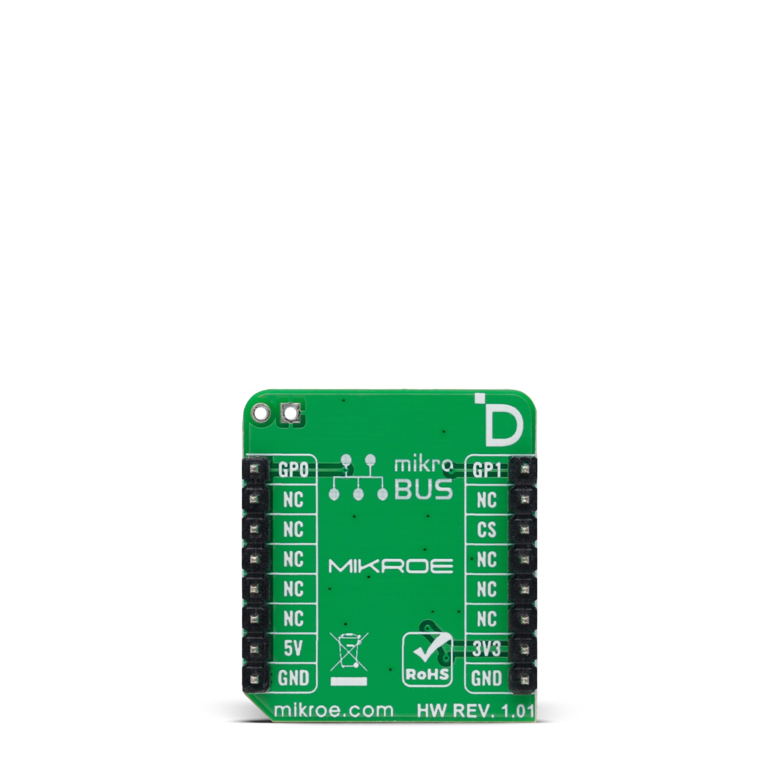
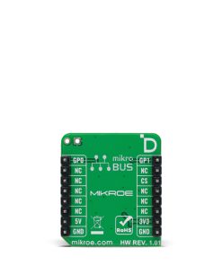
This table shows how the pinout on 1-Wire Switch Click corresponds to the pinout on the mikroBUS™ socket (the latter shown in the two middle columns).
Onboard settings and indicators
Label | Name | Default | Description |
---|---|---|---|
LD1 | PWR | – | Power LED Indicator |
LD2 | OUT | – | Output State LED Indicator |
JP1 | VCC SEL | Left | Logic Level Voltage Selection 3V3/5V: Left position 3V3, Right position 5V |
JP2 | I/O SEL | Left | Communication Pin Selection GP1/GP0: Left position GP1, Right position GP0 |
J1 | – | Unpopulated | External 1-Wire Device Connection Header |
T1 | – | – | Input State Button |
1-Wire Switch Click electrical specifications
Description | Min | Typ | Max | Unit |
---|---|---|---|---|
Supply Voltage | 3.3 | – | 5 | V |
Software Support
We provide a library for the 1-Wire Switch Click as well as a demo application (example), developed using Mikroe compilers. The demo can run on all the main Mikroe development boards.
Package can be downloaded/installed directly from NECTO Studio Package Manager(recommended way), downloaded from our LibStock™ or found on Mikroe github account.
Library Description
This library contains API for 1-Wire Switch Click driver.
Key functions
-
c1wireswitch_set_pio_state
1-Wire Switch write specific programmable I/O state function. -
c1wireswitch_get_pio_state
1-Wire Switch read specific programmable I/O state function. -
c1wireswitch_get_pio_latch_state
1-Wire Switch read programmable I/O latch state function.
Example Description
This library contains API for 1-Wire Switch Click driver. The library initializes and defines the 1-Wire bus drivers to
write and read data for state programmable I/O,
as well as the default configuration.
void application_task ( void )
{
uint8_t pio_a = 0;
uint8_t pio_b = 0;
c1wireswitch_get_pio_state( &c1wireswitch, &pio_a, &pio_b );
if ( pio_b == C1WIRESWITCH_PIOB_OFF )
{
if ( state == 0 )
{
c1wireswitch_set_pio_state( &c1wireswitch, C1WIRESWITCH_PIOA_ON, C1WIRESWITCH_PIOB_ON );
log_printf( &logger, " Button is pressed, LED is ON. rn " );
state = 1;
}
else
{
c1wireswitch_set_pio_state( &c1wireswitch, C1WIRESWITCH_PIOA_OFF, C1WIRESWITCH_PIOB_ON );
log_printf( &logger, " Button is pressed, LED is OFF. rn " );
state = 0;
}
Delay_ms( 100 );
}
Delay_ms( 100 );
}
The full application code, and ready to use projects can be installed directly from NECTO Studio Package Manager(recommended way), downloaded from our LibStock™ or found on Mikroe github account.
Other Mikroe Libraries used in the example:
- MikroSDK.Board
- MikroSDK.Log
- Click.c1WireSwitch
Additional notes and informations
Depending on the development board you are using, you may need USB UART click, USB UART 2 Click or RS232 Click to connect to your PC, for development systems with no UART to USB interface available on the board. A UART terminal is available in all Mikroe compilers.
mikroSDK
This Click board™ is supported with mikroSDK – Mikroe Software Development Kit, which needs to be downloaded from the LibStock and installed for the compiler you are using to ensure proper operation of mikroSDK compliant Click board™ demo applications.
For more information about mikroSDK, visit the official page.