Gyro Click
R525.00 R305.00 ex. VAT
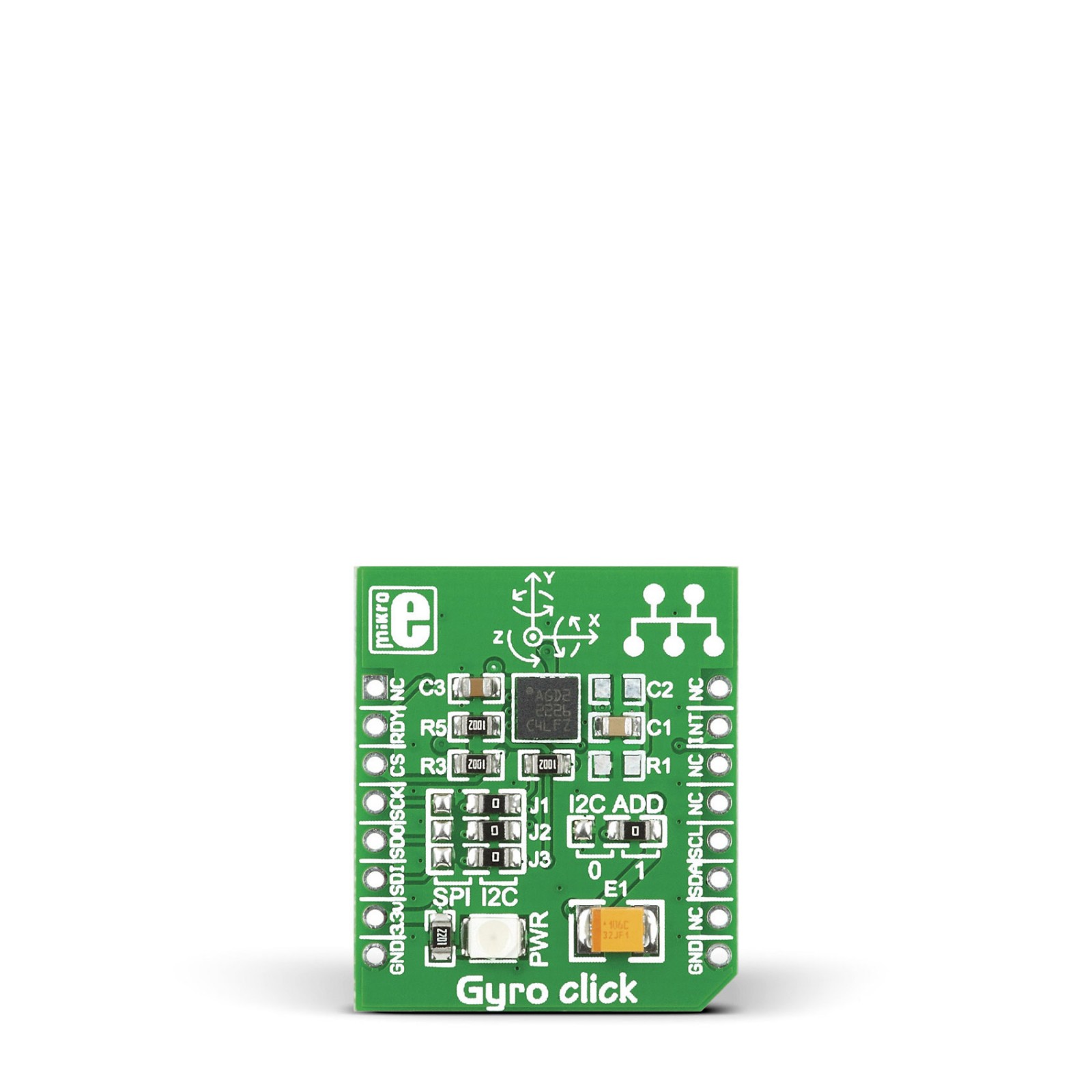
Gyro Click is a compact add-on board that contains a high-performance gyroscope. This board features the L3GD20, a low-power three-axis angular rate sensor (gyroscope) from STMicroelectronics. The L3GD20 is manufactured using a dedicated micro-machining process developed by STMicroelectronics to produce inertial sensors and actuators on silicon wafers. It provides a full-scale programmable range of ±250DPS, ±500DPS, and ±2000DPS, selectable sensitivity, and a configurable host interface that supports both SPI and I2C serial communication. This Click board™ is suitable for various applications such as angular velocity sensing, motion control with a man-machine interface, appliances, robotics, and many more.
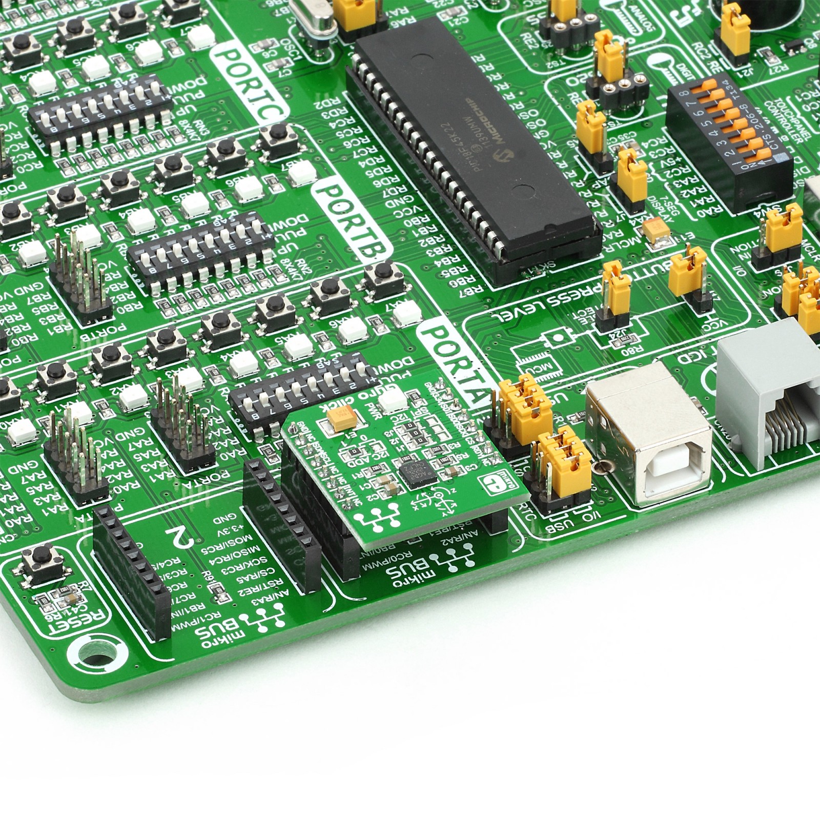
Gyro Click is supported by a mikroSDK compliant library, which includes functions that simplify software development. This Click board™ comes as a fully tested product, ready to be used on a system equipped with the mikroBUS™ socket.
Stock: 1 available immediately.
How does it work?
Gyro Click is based on the L3GD20, a high-performance 3-axis gyroscope from STMicroelectronics. The L3GD20 is manufactured using a dedicated micro-machining process developed by STMicroelectronics to produce inertial sensors and actuators on silicon wafers. It is highly configurable with a full-scale programmable range of ±250dps, ±500dps, and ±2000dps, i.e., low range for the high-precision measurement of slow motion and high range used for the measurement of ultra-rapid gestures and movements.
.jpg)
This Click board™ allows using both I2C and SPI interfaces with a maximum frequency of 400kHz for I2C and 10MHz for SPI communication. The selection can be made by positioning SMD jumpers labeled as COMM SEL in an appropriate position. Note that all the jumpers’ positions must be on the same side, or the Click board™ may become unresponsive. While the I2C interface is selected, the L3GD20 allows choosing the least significant bit (LSB) of its I2C slave address using the SMD jumper labeled as I2C ADD to an appropriate position marked as 0 and 1.
The L3GD20 embeds 32 slots of 16-bit data FIFO for each of the three output channels: yaw, pitch, and roll. This feature allows consistent power saving for the system since the host processor does not need to continuously poll data from the sensor but can wake up only when needed and burst the significant data out from the FIFO. This buffer can work in five modes: Bypass mode, FIFO mode, Stream mode, Bypass-to-Stream mode, and Stream-to-FIFO mode. Each mode is selected with the corresponding events detected on the interrupt and data-ready pins, routed to the INT and RST pins on the mikroBUS™ socket.
This Click board™ can be operated only with a 3.3V logic voltage level. The board must perform appropriate logic voltage level conversion before using MCUs with different logic levels. However, the Click board™ comes equipped with a library containing functions and an example code that can be used, as a reference, for further development.
Specifications
Type
Gyroscope,Motion
Applications
Can be used for various applications such as angular velocity sensing, motion control with a man-machine interface, appliances, robotics, and more
On-board modules
L3GD20 – 3-axis gyroscope from STMicroelectronics
Key Features
Low power consumption, full-scale programmable range up to ±2000dps, configurable host interface, integrated temperature sensor, programmable interrupts, high performance, reliability, and more
Interface
I2C,SPI
Feature
No ClickID
Compatibility
mikroBUS™
Click board size
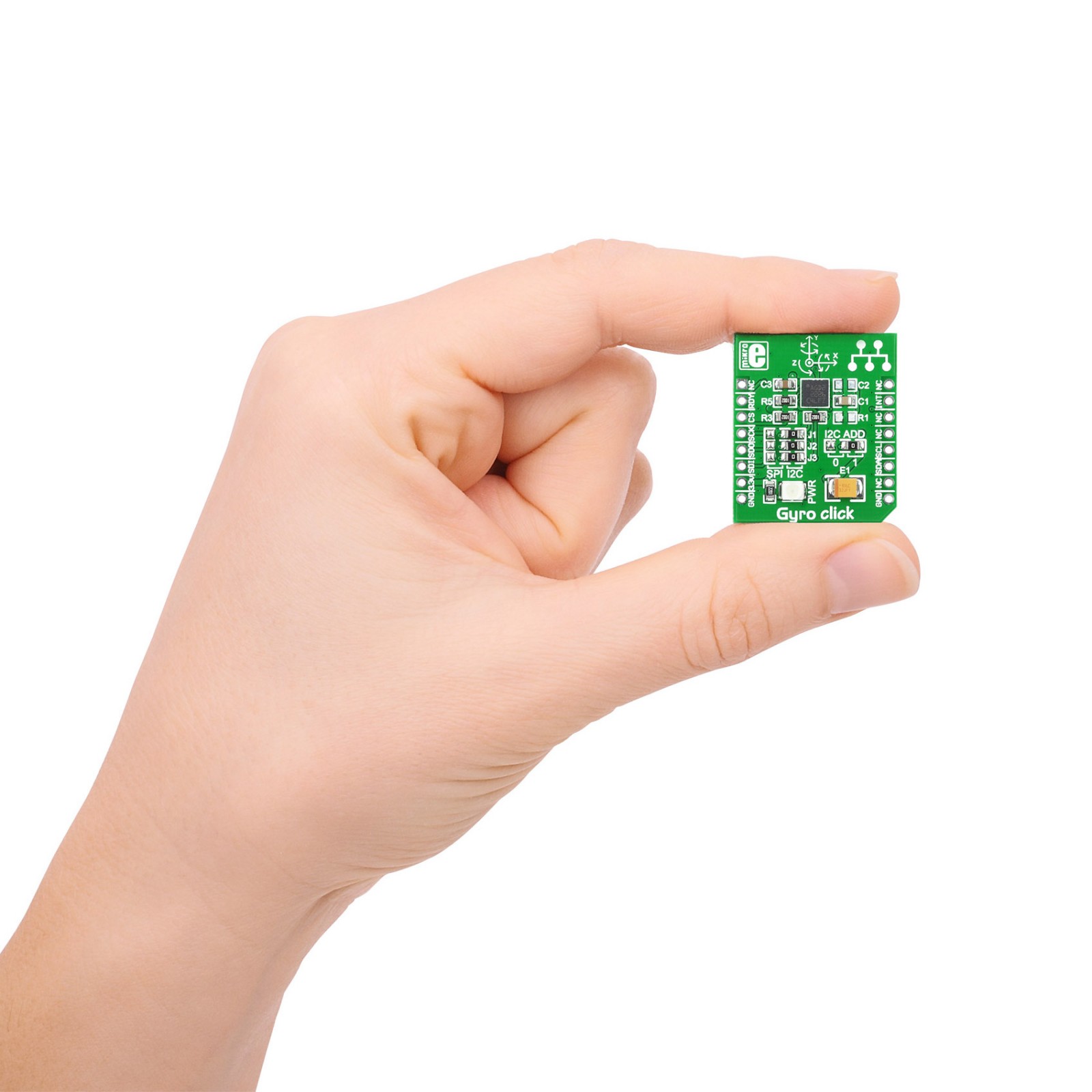
S (28.6 x 25.4 mm)
Input Voltage
3.3V
Pinout diagram
This table shows how the pinout on Gyro Click corresponds to the pinout on the mikroBUS™ socket (the latter shown in the two middle columns).
Onboard settings and indicators
| Label | Name | Default | Description |
|---|---|---|---|
| LD1 | PWR | – | Power LED Indicator |
| JP1-JP3 | COMM SEL | Right | Communication Interface Selection SPI/I2C: Left position SPI, Right position I2C |
| JP4 | I2C ADD | Left | I2C Address Selection 1/0: Left position 1, Right position 0 |
Gyro Click electrical specifications
| Description | Min | Typ | Max | Unit |
|---|---|---|---|---|
| Supply Voltage | – | 3.3 | – | V |
| Full-Scale Range | ±250 | – | ±2000 | dps |
| Sensitivity | 8.75 | – | 70 | LSB/dps |
Software Support
We provide a library for the Gyro Click as well as a demo application (example), developed using MikroElektronika compilers. The demo can run on all the main MikroElektronika development boards.
Package can be downloaded/installed directly from NECTO Studio Package Manager(recommended way), downloaded from our LibStock™ or found on Mikroe github account.
Library Description
This library contains API for Gyro Click driver.
Key functions
-
Function get data from two L3GD20 register.
-
Function read Gyro X-axis, Y-axis and Z-axis axis.
-
Function read temperature data.
Example Description
This example displays values of Gyro sensor (x, y, z axis)
 void application_task ( void )
 {
     //  Task implementation.

     gyro_read_gyro(  &gyro, &gyrox,  &gyroy, &gyroz );
     temperature = gyro_read_temperature( &gyro );

     log_printf( &logger, " Axis X : %d rn", gyrox );
     log_printf( &logger, " Axis Y : %d rn", gyroy );
     log_printf( &logger, " Axis Z : %d rn", gyroz );
     log_printf( &logger, " Temp.: %.2f Crn", temperature );

     Delay_ms( 2000 );
 }
The full application code, and ready to use projects can be installed directly from NECTO Studio Package Manager(recommended way), downloaded from our LibStock™ or found on Mikroe github account.
Other Mikroe Libraries used in the example:
- MikroSDK.Board
- MikroSDK.Log
- Click.Gyro
Additional notes and informations
Depending on the development board you are using, you may need USB UART click, USB UART 2 Click or RS232 Click to connect to your PC, for development systems with no UART to USB interface available on the board. UART terminal is available in all MikroElektronika compilers.
mikroSDK
This Click board™ is supported with mikroSDK – MikroElektronika Software Development Kit. To ensure proper operation of mikroSDK compliant Click board™ demo applications, mikroSDK should be downloaded from the LibStock and installed for the compiler you are using.
For more information about mikroSDK, visit the official page.
Resources
Downloads
| Weight | 30 g |
|---|---|
| Brand | MikroElektronika |

