GSM/GNSS 2 Click
R1,400.00 ex. VAT
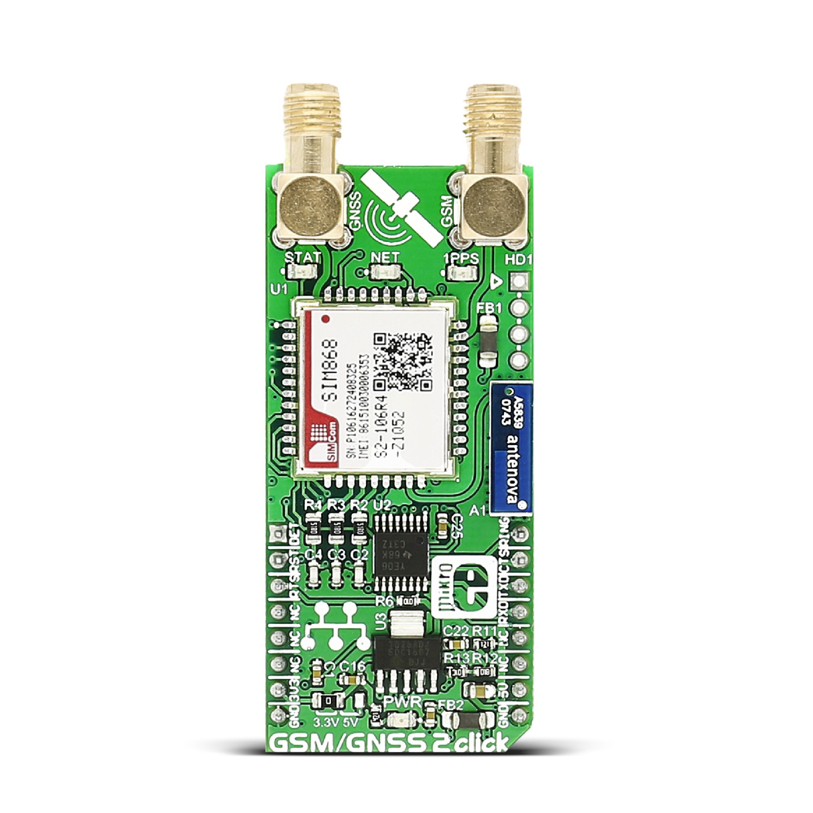
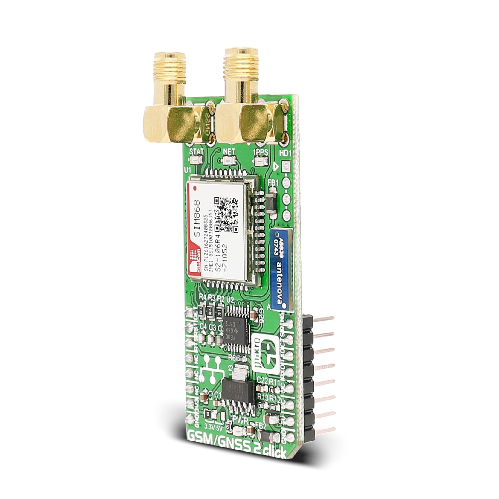
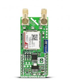
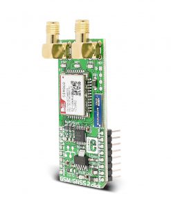
GSM/GNSS 2 Click is a compact add-on board that combines GPS/GLONASS location tracking with GSM module capability for mobile communication. This board features the SIM868, a high-performance GSM/GPRS module from SIMCom. It offers extensive internet protocols and integrates GNSS technology for satellite navigation. The module provides much flexibility and ease of integration for customers’ applications. It communicates with the target MCU over the UART interface and offers a complete range of SMS and data transmission services to meet client-side demands. This Click board™ is suitable for many M2M applications, asset tracking, navigation devices based on GPS and GLONASS, automotive, and many more.
GSM/GNSS 2 Click is supported by a mikroSDK compliant library, which includes functions that simplify software development. This Click board™ comes as a fully tested product, ready to be used on a system equipped with the mikroBUS™ socket.
Stock: Lead-time applicable.
| 5+ | R1,330.00 |
| 10+ | R1,260.00 |
| 15+ | R1,190.00 |
| 20+ | R1,145.20 |
How does it work?
GSM/GNSS 2 Click as its foundation uses the SIM868, a multi-purpose module that integrates a high-performance GNSS engine and a GSM/GPRS engine from SIMCom. The quad-band GSM/GPRS engine can work at 850, 900, 1800, and 1900MHz. It also features GPRS multi-slot class 12 and supports the GPRS coding schemes CS-1, CS-2, CS-3, and CS-4. The GNSS solution offers best-in-class acquisition and tracking sensitivity, Time-To-First-Fix (TTFF), and accuracy. The GSM part of the SIM868 is integrated with Internet service protocols such as TCP, UDP, PPP, HTTP, and FTP. The excellent positioning performance, low power consumption, and dual μSIM card interfaces make SIM868 the superb choice for many M2M applications.
The SIM868 module has to be powered by a clean and stable power supply. The voltage needed for the module to work correctly is 4V, and it is derived from the 5V mikroBUS™ power rail through the MCP1826, a 1A low drop output (LDO) regulator. The main 4V power supply is also the power supply for the GSM/GNSS block of the SIM868. Also, activation of the module itself is possible via the RST pin on the mikroBUS™ socket connected to the PWRKEY pin of the module used for turning the module ON and OFF.
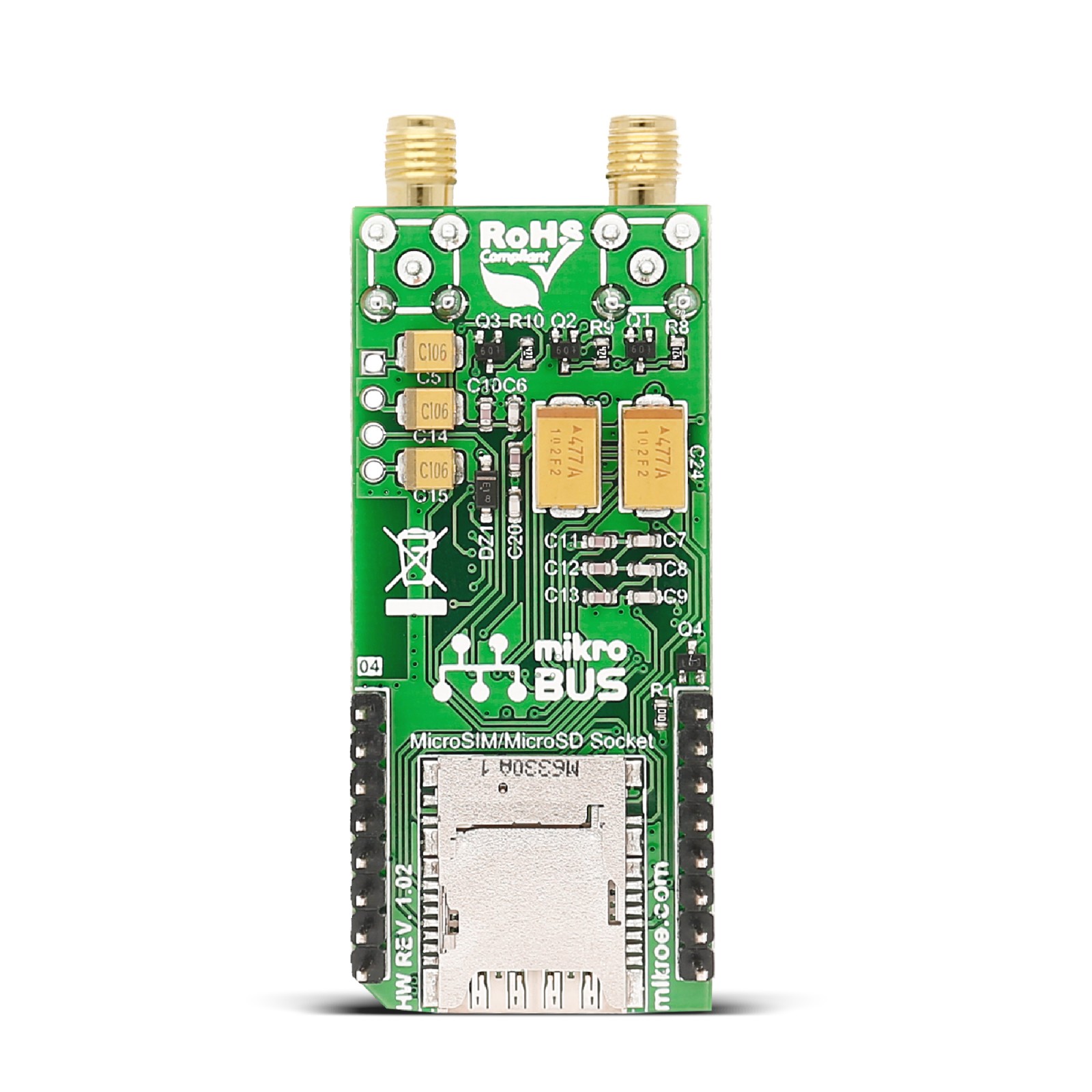
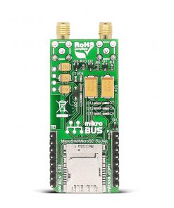
The SIM868 communicates with MCU using the UART interface with commonly used UART RX and TX pins with the hardware flow control pins UART CTS, RTS, RI (Clear to Send, Ready to Send, and Ring Indicator). The GSM/GNSS 2 Click also has an onboard MicroSD/MicroSIM card socket with card detection feature routed to the AN pin on the mikroBUS™ socket, A5839 Bluetooth 3.0 2.4GHz chip antenna, which the SIM868 module version supports, and an additional header labeled as HD1 for audio interface (channels for connecting speakers and a microphone). In addition to all these features, this Click board™ also has three yellow LED indicators labeled as NET, STAT, and 1PPS. The network status NET indicates if the module is attached or not to a network, Power-ON Status STAT indicates the operating status of the module, and successfully positioning 1PPS shows one pulse per second synchronized to GNSS satellites.
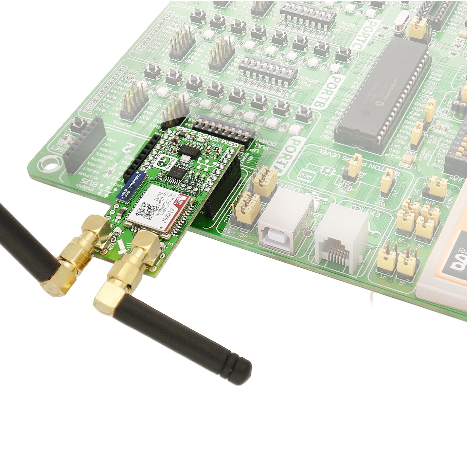
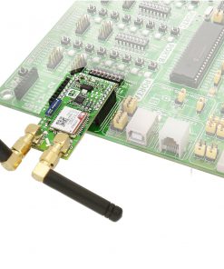
Furthermore, it possesses two SMA antenna connectors with an impedance of 50Ω, labeled as GNSS and GSM, used for connecting the appropriate antenna that Mikroe has in its offer. When connected to a GPS antenna, it can receive GPS coordinates, time, and other information from orbiting satellites. The Click board™ can be used for all GSM functions — calls, messages (SMS, MMS), mobile internet.
NOTE: To ensure the proper operation of the GNSS part, it is necessary to use only a GPS&GLONASS External Passive antenna that the user can also find in our offer.
This Click board™ can operate with both 3.3V and 5V logic voltage levels and comes with a proper logic voltage level conversion performed by the appropriate voltage level translator TXB0106. This way, it is allowed for both 3.3V and 5V capable MCUs to use the UART communication lines properly. However, the Click board™ comes equipped with a library containing easy-to-use functions and an example code that can be used, as a reference, for further development.
Specifications
Type
2G GPRS,GSM+GPS
Applications
Can be used for a wide range of M2M applications, asset tracking, navigation devices based on GPS and GLONASS, automotive, and many more
On-board modules
SIM868 – multi-purpose module that integrates a high-performance GNSS engine and a GSM/GPRS engine from SIMCom
Key Features
GPS/GLONASS location tracking with GSM module capability, an extensive set of internet protocols, high accuracy, high performance, low power consumption, offers a complete range of SMS and data transmission, and more
Interface
GPIO,UART
Feature
No ClickID
Compatibility
mikroBUS™
Click board size
L (57.15 x 25.4 mm)
Input Voltage
3.3V or 5V
Pinout diagram
This table shows how the pinout on GSM/GNSS 2 Click corresponds to the pinout on the mikroBUS™ socket (the latter shown in the two middle columns).
Onboard settings and indicators
| Label | Name | Default | Description |
|---|---|---|---|
| LD1 | PWR | – | Power LED Indicator |
| LD2 | STATUS | – | Power-ON Status LED Indicator |
| LD3 | NET | – | Network Status LED Indicator |
| LD4 | 1PPS | – | Successfully Positioning LED Indicator |
| JP1 | – | Left | Logic Level Voltage Selection 3V3/5V: Left position 3V3, Right position 5V |
| J1 | HD1 | Unpopulated | Audio Interface Header |
GSM/GNSS 2 Click electrical specifications
| Description | Min | Typ | Max | Unit |
|---|---|---|---|---|
| Supply Voltage | 3.3 | – | 5 | V |
| Operating Frequency Range | 850 | – | 1900 | MHz |
| Operating Temperature Range | -40 | +25 | +85 | °C |
Software Support
We provide a library for the GSM/GNSS 2 Click as well as a demo application (example), developed using MIKROE compilers. The demo can run on all the main MIKROE development boards.
Package can be downloaded/installed directly from NECTO Studio Package Manager(recommended), downloaded from our LibStock™ or found on Mikroe github account.
Library Description
This library contains API for GSM/GNSS 2 Click driver.
Key functions
-
gsmgnss2_send_cmdSend command function. -
gsmgnss2_set_sim_apnSet sim card APN. -
gsmgnss2_send_sms_pduGSM GNSS send SMS in PDU mode.
Example Description
This example reads and processes data from GSM/GNSS 2 clicks.
void application_task ( void )
 {
     if ( app_connection_status == WAIT_FOR_CONNECTION )
     {
         // CREG - network registration status
         gsmgnss2_send_cmd_check( &gsmgnss2, GSMGNSS2_CMD_CREG );
         app_error_flag = gsmgnss2_rsp_check(  );
         gsmgnss2_error_check( app_error_flag );
         Delay_ms ( 500 );

         // CSQ - signal quality
         gsmgnss2_send_cmd( &gsmgnss2, GSMGNSS2_CMD_CSQ );
         app_error_flag = gsmgnss2_rsp_check(  );
         gsmgnss2_error_check( app_error_flag );
         Delay_ms ( 1000 );
         Delay_ms ( 1000 );
         Delay_ms ( 1000 );
         Delay_ms ( 1000 );
         Delay_ms ( 1000 );
     }
     else
     {
         log_info( &logger, "CONNECTED TO NETWORK" );

         for ( ; ; )
         {
             // Get GNSS info
             gnss_parser_flag = 1;
             gsmgnss2_send_cmd_with_parameter( &gsmgnss2, GSMGNSS2_CMD_CGNSTST, "1" );

             for ( ; ; )
             {
                 if ( GSMGNSS2_OK == gsmgnss2_process( ) )
                 {
                     gnss_parser_application( app_buf );

                     if ( gnss_parser_flag == 2 )
                     {
                         gsmgnss2_send_cmd_with_parameter( &gsmgnss2, GSMGNSS2_CMD_CGNSTST, "0" );
                         app_error_flag = gsmgnss2_rsp_check(  );
                         gsmgnss2_error_check( app_error_flag );
                         log_printf( &logger, "> Sending message to phone number...rn" );
                         gsmgnss2_send_sms_pdu ( &gsmgnss2, SIM_SMSC, PHONE_NUMBER_TO_MESSAGE, gnss_info_message );
                         app_error_flag = gsmgnss2_rsp_check(  );
                         gsmgnss2_error_check( app_error_flag );
                         Delay_ms ( 1000 );
                         Delay_ms ( 1000 );
                         Delay_ms ( 1000 );
                         Delay_ms ( 1000 );
                         Delay_ms ( 1000 );
                         Delay_ms ( 1000 );
                         Delay_ms ( 1000 );
                         Delay_ms ( 1000 );
                         Delay_ms ( 1000 );
                         Delay_ms ( 1000 );
                         Delay_ms ( 1000 );
                         Delay_ms ( 1000 );
                         Delay_ms ( 1000 );
                         Delay_ms ( 1000 );
                         Delay_ms ( 1000 );
                         Delay_ms ( 1000 );
                         Delay_ms ( 1000 );
                         Delay_ms ( 1000 );
                         Delay_ms ( 1000 );
                         Delay_ms ( 1000 );
                         Delay_ms ( 1000 );
                         Delay_ms ( 1000 );
                         Delay_ms ( 1000 );
                         Delay_ms ( 1000 );
                         Delay_ms ( 1000 );
                         Delay_ms ( 1000 );
                         Delay_ms ( 1000 );
                         Delay_ms ( 1000 );
                         Delay_ms ( 1000 );
                         Delay_ms ( 1000 );
                     }
                     if ( gnss_parser_flag != 1 )
                     {
                         break;
                     }
                 }
             }
         }
     }
 }
The full application code, and ready to use projects can be installed directly from NECTO Studio Package Manager(recommended), downloaded from our LibStock™ or found on Mikroe github account.
Other Mikroe Libraries used in the example:
- MikroSDK.Board
- MikroSDK.Log
- Click.GSMGNSS2
Additional notes and informations
Depending on the development board you are using, you may need USB UART click, USB UART 2 Click or RS232 Click to connect to your PC, for development systems with no UART to USB interface available on the board. UART terminal is available in all MIKROE compilers.
mikroSDK
This Click board™ is supported with mikroSDK – MIKROE Software Development Kit. To ensure proper operation of mikroSDK compliant Click board™ demo applications, mikroSDK should be downloaded from the LibStock and installed for the compiler you are using.
For more information about mikroSDK, visit the official page.
Resources
Downloads
| Weight | 28 g |
|---|---|
| Brand | MikroElektronika |

