How does it work?
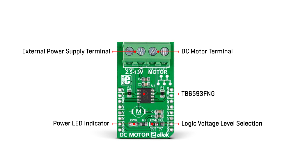
DC Motor 2 Click is based on the TB6593FNG, full-bridge brushed DC motor driver from Toshiba Semiconductor. The TB6593FNG comes in a configuration with an output transistor in LD MOS structure with low on-resistance (0.35Ω typical with 5V power supply). It has a wide operating voltage range with an output current capacity of 1A maximum and control functions, including motor-related and built-in protection circuits such as thermal shutdown and low voltage detecting.
This Click board™ is a PWM-controlled type with the ability for motor control through several pins of the mikroBUS™ socket. The PWM signal of the mikroBUS™ socket drives the motor while the IN1 and IN2 pins, routed on the CS and RST pins of the mikroBUS™ socket, provide binary direction signals that set the direction of the motor (clockwise or counterclockwise) or apply stop or short brake functions. Stop mode cuts off the power supply, so the motor continues spinning until it runs out of momentum, while a short break brings it to an abrupt stop. Alongside the PWM pin from the mikroBUS™ socket, used to drive a DC motor, this Click board™ also has a Standby pin labeled as SLP and routed to the INT pin of the mikroBUS™ socket to optimize power consumption used for power save purposes.
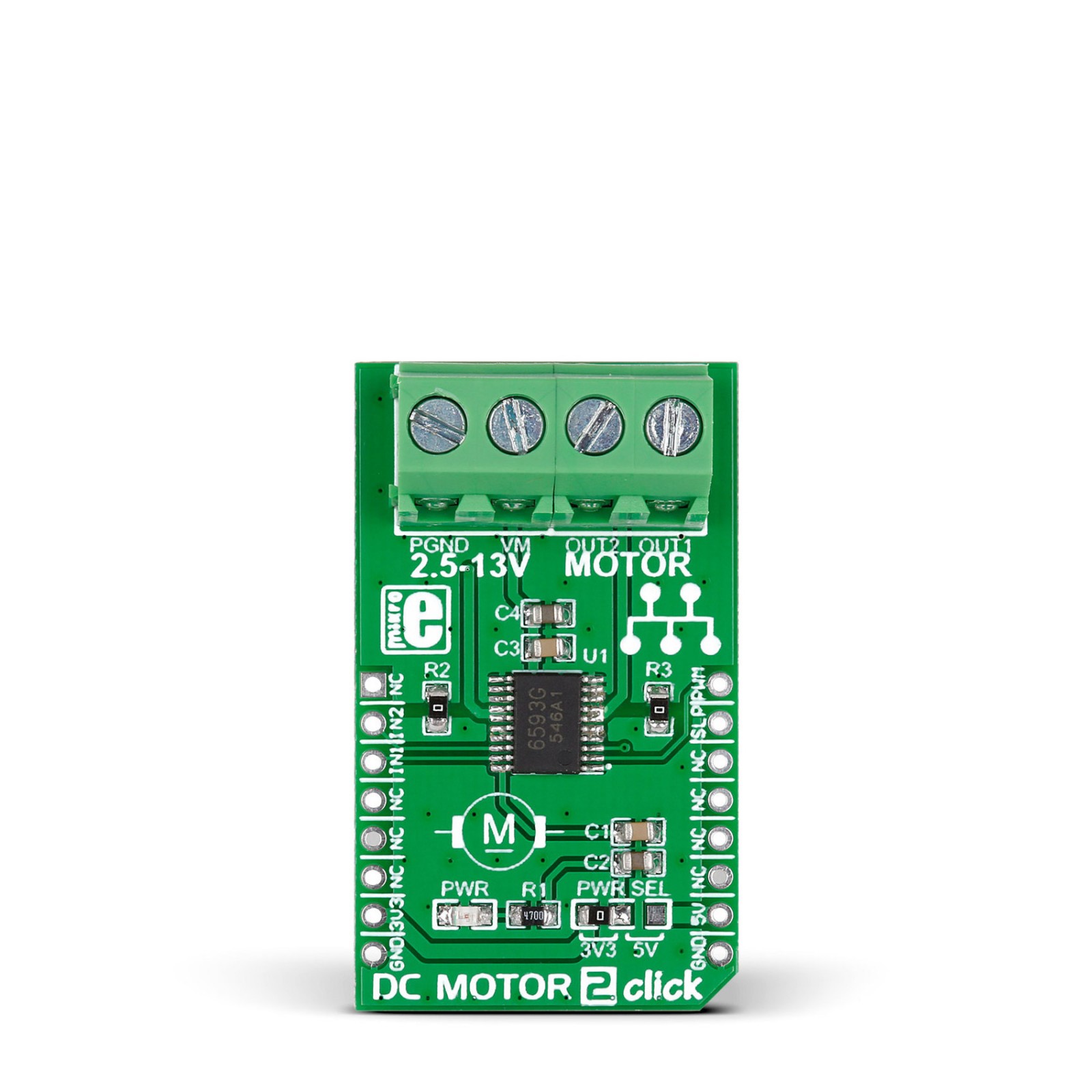
DC Motor 2 Click supports an external power supply for the TB6593FNG, which can be connected to the input terminal labeled as VM and should be within the range of 2.5V to 13V, while the DC motor coils can be connected to the terminals labeled as OUT1 and OUT2.
This Click board™ can operate with both 3.3V and 5V logic voltage levels selected via the PWR SEL jumper. This way, it is allowed for both 3.3V and 5V capable MCUs to use the communication lines properly. However, the Click board™ comes equipped with a library containing easy-to-use functions and an example code that can be used, as a reference, for further development.
Specifications
Type
Brushed
Applications
Can be used for driving DC brushed motors in general-purpose applications with relatively higher voltage requirements
On-board modules
TB6593FNG – brushed DC motor driver from Toshiba Semiconductor
Key Features
Full-bridge driver for one DC motor, PWM control, selectable motor operational modes, Standby Power-save mode, full protection features, and more
Interface
GPIO,PWM
Feature
No ClickID
Compatibility
mikroBUS™
Click board size
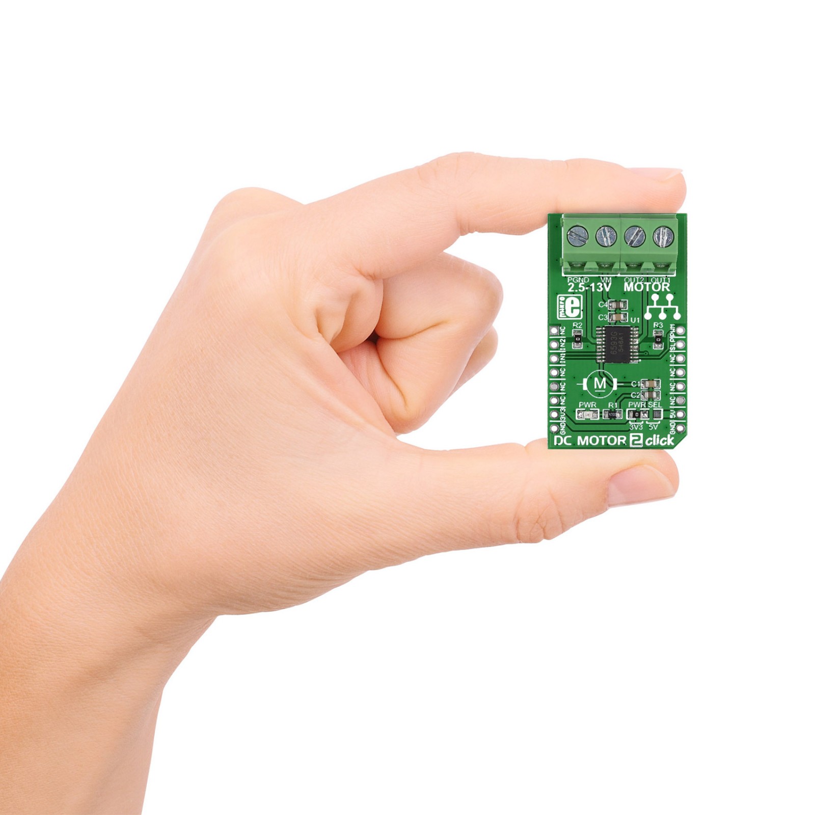
M (42.9 x 25.4 mm)
Input Voltage
3.3V or 5V,External
Pinout diagram
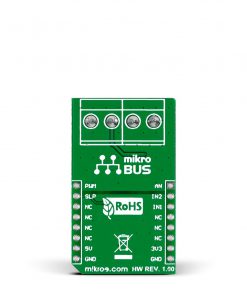
This table shows how the pinout on DC MOTOR 2 Click corresponds to the pinout on the mikroBUS™ socket (the latter shown in the two middle columns).
Onboard settings and indicators
Label | Name | Default | Description |
---|---|---|---|
LD1 | PWR | – | Power LED Indicator |
JP1 | PWR SEL | Left | Logic Level Voltage Selection 3V3/5V: Left position 3V3, Right position 5V |
DC MOTOR 2 Click electrical specifications
Description | Min | Typ | Max | Unit |
---|---|---|---|---|
Supply Voltage | 3.3 | – | 5 | V |
External Power Supply | 2.5 | – | 13 | V |
Output Current | – | – | 1 | A |