How does it work?
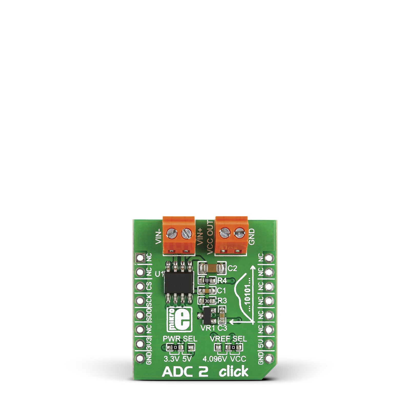
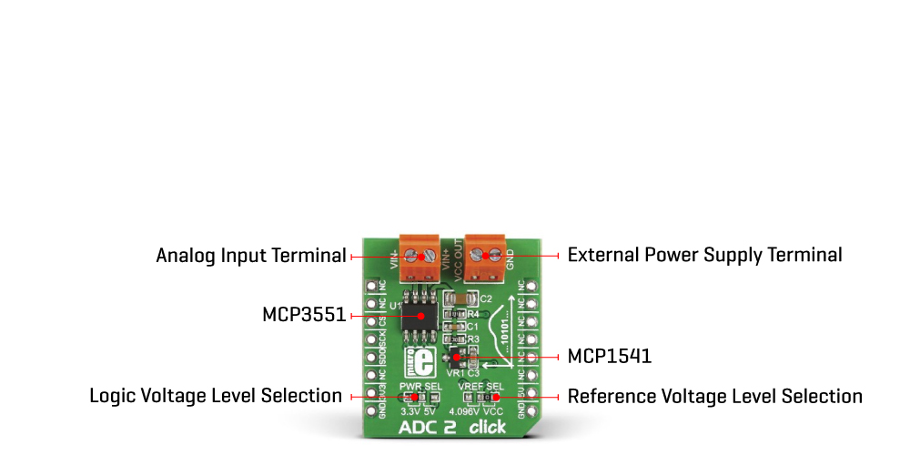
ADC 2 Click is based on the MCP3551, a 22-bit precise single-channel ΔΣ analog-to-digital converter from Microchip. The MCP3551 includes fully differential analog input on a VIN terminal, a third-order delta-sigma modulator, a fourth-order modified SINC decimation filter (allows superior averaging performance), an on-chip, low-noise internal oscillator, a power supply monitoring circuit, and an SPI digital interface. It can be easily used to measure low-frequency, low-level signals such as those found in pressure transducers, temperature, strain gauges, industrial control, or process control applications.
This Click board™ communicates with MCU through a 3-Wire SPI interface (read-only) with a maximum frequency of 5MHz. The interface offers two conversion modes: A single Conversion mode for multiplexed applications and a Continuous Conversion mode for multiple conversions in series, where every conversion is independent of each other (all internal registers are flushed between conversions). When the MCP3551 is not converting, it automatically goes into Shutdown mode, characterized by low power consumption.
The MCP3551 provides single-cycle conversions with no digital filter settling time. Every conversion includes an internal offset and gain auto-calibration to reduce device error, which is transparent to the user and done in real-time during the conversion, allowing multiplexed applications. Like any ADC, the MCP3551 uses a reference voltage as the differential voltage range. The reference voltage level selection is performed by positioning the SMD jumper labeled as VREF SEL to an appropriate position choosing between 3.3V or 5V provided by the mikroBUS™ power rails or 4.096V provided by MCP1541. Those voltages may be used as the reference input that results in accuracy and stability.
Besides, the ADC 2 Click supports an external power supply for the MCP3551, which can be connected to the input terminal labeled as VCC OUT and should be within the range of 2.7V to 5.5V.
This Click board™ can operate with both 3.3V and 5V logic voltage levels selected via the PWR SEL jumper. This way, it is allowed for both 3.3V and 5V capable MCUs to use the communication lines properly. However, the Click board™ comes equipped with a library containing easy-to-use functions and an example code that can be used, as a reference, for further development.
Specifications
Type
ADC
Applications
Can be used for most demanding applications, from general-purpose remote data acquisition to industrial applications
On-board modules
MCP3551 – 22-bit precision ΔΣ analog-to-digital converter from Microchip
Key Features
Low power consumption, high accuracy, low noise performance, fully differential analog input, internal offset and gain calibration, reference voltage selection, and more
Interface
SPI
Feature
No ClickID
Compatibility
mikroBUS™
Click board size
S (28.6 x 25.4 mm)
Input Voltage
3.3V or 5V
Pinout diagram
This table shows how the pinout on ADC 2 Click corresponds to the pinout on the mikroBUS™ socket (the latter shown in the two middle columns).
Onboard settings and indicators
Label | Name | Default | Description |
---|---|---|---|
JP1 | VREF SEL | Right | Reference Level Voltage Selection 4.096V/VCC: Left position 4.096V, Right position VCC |
JP2 | PWR SEL | Left | Logic Level Voltage Selection 3V3/5V: Left position 3V3, Right position 5V |
ADC 2 Click electrical specifications
Description | Min | Typ | Max | Unit |
---|---|---|---|---|
Supply Voltage | 3.3 | – | 5 | V |
External Supply Voltage | 2.7 | – | 5.5 | V |
Resolution | – | 22 | – | bit |
Data Rate | – | 13.75 | – | Hz |
Software Support
We provide a library for the ADC 2 Click as well as a demo application (example), developed using Mikroe compilers. The demo can run on all the main Mikroe development boards.
Package can be downloaded/installed directly from NECTO Studio Package Manager(recommended), downloaded from our LibStock™ or found on Mikroe github account.
Library Description
This library contains API for ADC 2 Click driver.
Key functions
-
Function is used to check overflow high state.
-
Function is used to check overflow low state.
-
Function is used to read specific data from ADC convertor.
Example Description
This application enables usage of the 22bit ADC.
void application_task ( void )
{
uint32_t adc_val;
// Task implementation.
adc_val = adc2_adc_value_read( &adc2 );
log_printf( &logger, "Value : %d", adc_val );
log_printf( &logger, "------------------rn" );
Delay_ms( 1000 );
}
The full application code, and ready to use projects can be installed directly from NECTO Studio Package Manager(recommended), downloaded from our LibStock™ or found on Mikroe github account.
Other Mikroe Libraries used in the example:
- MikroSDK.Board
- MikroSDK.Log
- Click.Adc2
Additional notes and informations
Depending on the development board you are using, you may need USB UART click, USB UART 2 Click or RS232 Click to connect to your PC, for development systems with no UART to USB interface available on the board. UART terminal is available in all Mikroe compilers.
mikroSDK
This Click board™ is supported with mikroSDK – Mikroe Software Development Kit. To ensure proper operation of mikroSDK compliant Click board™ demo applications, mikroSDK should be downloaded from the LibStock and installed for the compiler you are using.
For more information about mikroSDK, visit the official page.