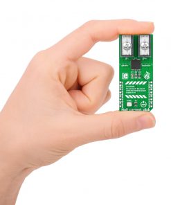
Hall current Click
R725.00 R420.00 ex. VAT
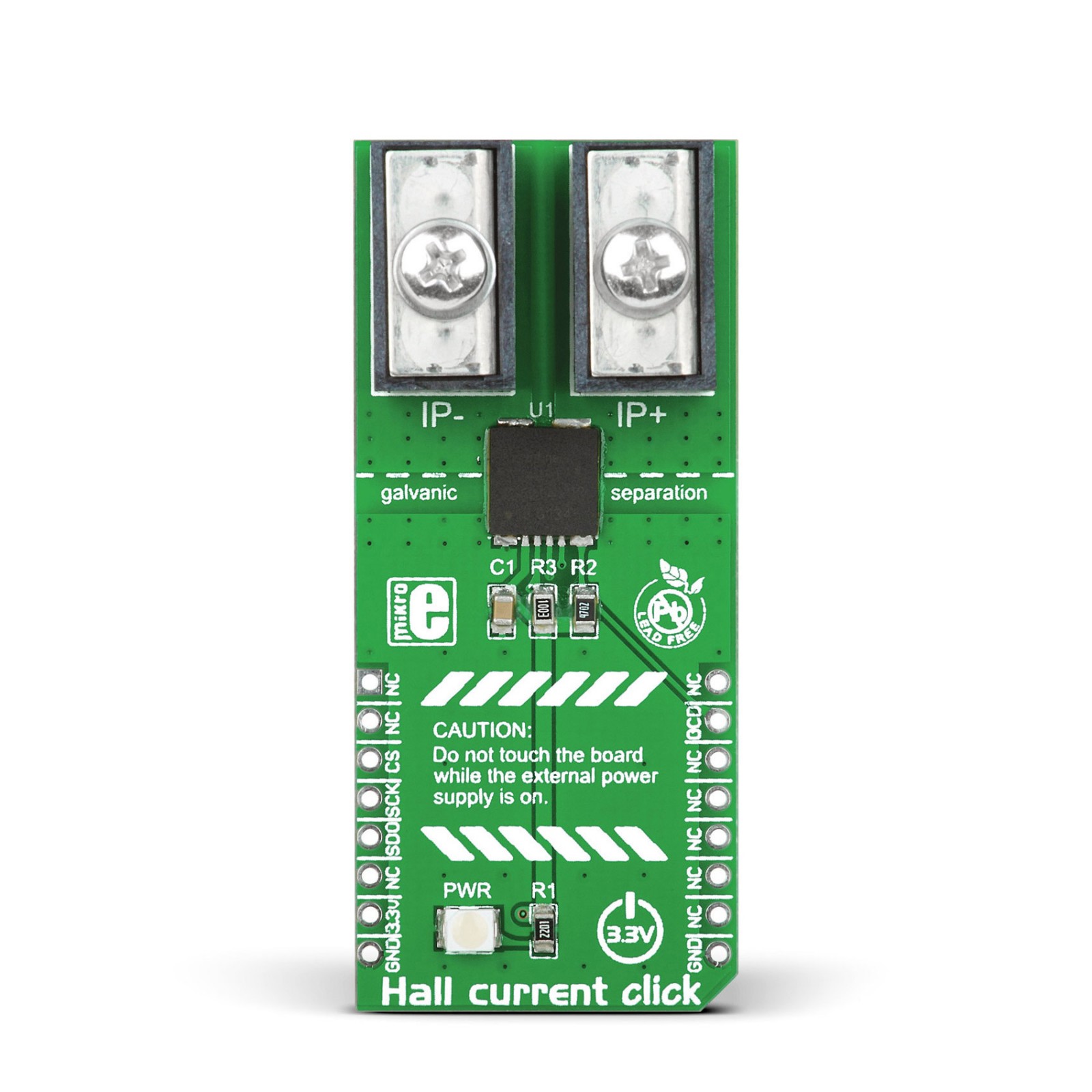
Hall Current Click is a compact add-on board that contains a precise solution for AC/DC current sensing. This board features the TLI4970-D050T4, a 16-bit digital SPI output (13-bit current value) coreless magnetic current sensor designed for the current range of ±25A from Infineon Technology. A differential measurement principle allows effective stray field suppression with a highly linear output signal without hysteresis. Due to the integrated primary conductor (current rail), there is no need for external calibration. The TLI4970-D050T4 is highly accurate over temperature range and lifetime with fast overcurrent detection with a configurable threshold. This Click board™ is suitable for AC and DC current measurement applications such as current monitoring, chargers and general purpose inverters, power supplies, and more.
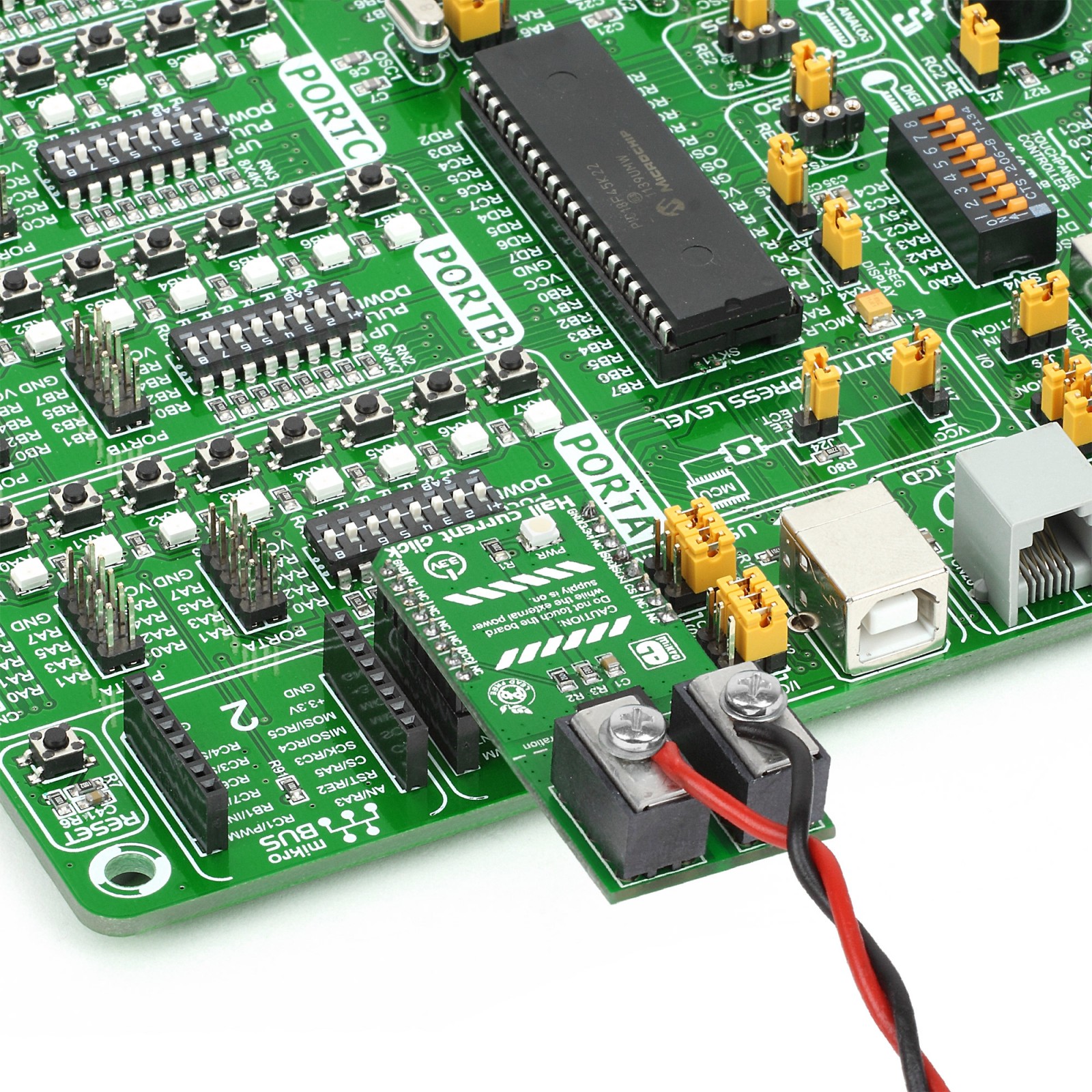
Hall Current Click is supported by a mikroSDK compliant library, which includes functions that simplify software development. This Click board™ comes as a fully tested product, ready to be used on a system equipped with the mikroBUS™ socket.
Stock: 1 available immediately.
 DO NOT TOUCH THE BOARD WHILE THE LOAD IS CONNECTED!
Note: This Click board™ needs to be used by trained personnel only while applying high voltages. Special care should be taken when working with hazardous voltage levels.
How does it work?
Hall Current Click, as its foundation, uses the TLI4970-D050T4, a high-precision digital current sensor designed for the current range of ±25A from Infineon Technology. The measurement principle allows galvanic isolation (functional isolation) between the primary conductor and the secondary interface. Based on a digital concept, the signal processing unit of the TLI4970-D050T4 already has integrated compensation and calibration, which means no further external measurements for compensation are needed. It represents a plug-and-play solution, easy to use in industrial and consumer applications.
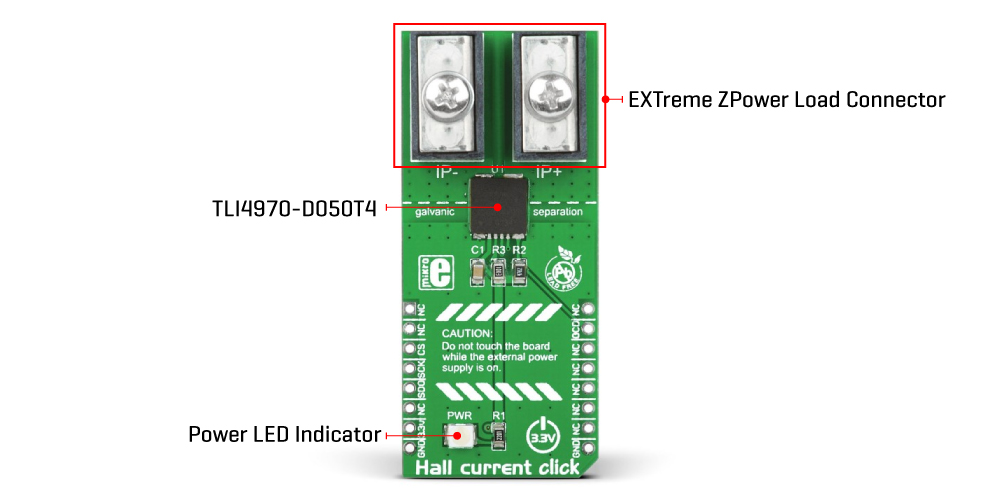
The differential measurement principle of the TLI4970-D050T4 achieves best-in-class suppression of stray magnetic fields with a highly linear output signal without hysteresis. The accuracy of the TLI4970-D050T4 is comparable to closed-loop current measurement systems and even better than open-loop systems with magnetic cores. But in comparison to the open- and closed-loop systems, the TLI4970-D050T4 enables significantly less power consumption. Besides outstanding long-term stability of the output signal and a proprietary dynamic offset cancellation technique that guarantees low zero point error, the TLI4970-D050T4 offers superior performance.
As mentioned before, this Click board™ communicates with MCU through a standard unidirectional 16-bit SPI protocol used to control and configure the TLI4970-D050T4 with a maximum SPI frequency of 5MHz. In addition to communication pins, this board also possesses an additional pin marked as OCD, routed to the INT pin on the mikroBUS™ socket for over-current detection. For fast over-current detection, the raw analog signal from the Hall probes is fed into a programmable comparator with a programmable glitch filter to suppress the signal’s fast switching transients and avoid false triggers.
This Click board™ can be operated only with a 3.3V logic voltage level. The board must perform appropriate logic voltage level conversion before using MCUs with different logic levels. However, the Click board™ comes equipped with a library containing functions and an example code that can be used, as a reference, for further development.
Specifications
Type
Current sensor,Measurements
Applications
Can be used for current monitoring, chargers and general purpose inverters, power supplies, and more
On-board modules
TLI4970-D050T4 – high-precision digital current sensor from Infineon Technology
Key Features
AC-DC measurement range up to ±25A, highly accurate over temperature range and lifetime, low offset error, high magnetic field suppression, fast over-current detection with configurable threshold, SPI interface, and more
Interface
GPIO,SPI
Feature
No ClickID
Compatibility
mikroBUS™
Click board size
L (57.15 x 25.4 mm)
Input Voltage
3.3V
Pinout diagram
This table shows how the pinout on Hall current Click corresponds to the pinout on the mikroBUS™ socket (the latter shown in the two middle columns).
Onboard settings and indicators
| Label | Name | Default | Description |
|---|---|---|---|
| LD1 | PWR | – | Power LED Indicator |
Hall current Click electrical specifications
| Description | Min | Typ | Max | Unit |
|---|---|---|---|---|
| Supply Voltage | – | 3.3 | – | V |
| Measurement Range | -25 | – | +25 | A |
| Accuracy | – | ±1.6 | – | % |
| Isolation Voltage | – | – | 2545 | Vrms |
| Operating Temperature Range | -40 | +25 | +85 | °C |
Software Support
We provide a library for the Hall Current Click as well as a demo application (example), developed using MikroElektronika compilers. The demo can run on all the main MikroElektronika development boards.
Package can be downloaded/installed directly from NECTO Studio Package Manager(recommended way), downloaded from our LibStock™ or found on Mikroe github account.
Library Description
This library contains API for Hall Current Click driver.
Key functions
-
Generic read 16-bit data function
-
Check status of read data function.
-
Read electric current function
Example Description
The application is current sensor.
 void application_task ( void )
 {
     float current_read_float;
     current_read_float = hallcurrent_read_current( &hallcurrent );

     Delay_ms( 100 );

     log_printf( &logger, " Current : %f ", current_read_float );
     log_printf( &logger, " [ A ] rn" );
     log_printf( &logger, "------------------------rn" );

     Delay_ms( 5000 );
 }
The full application code, and ready to use projects can be installed directly from NECTO Studio Package Manager(recommended way), downloaded from our LibStock™ or found on Mikroe github account.
Other Mikroe Libraries used in the example:
- MikroSDK.Board
- MikroSDK.Log
- Click.HallCurrent
Additional notes and informations
Depending on the development board you are using, you may need USB UART click, USB UART 2 Click or RS232 Click to connect to your PC, for development systems with no UART to USB interface available on the board. UART terminal is available in all MikroElektronika compilers.
mikroSDK
This Click board™ is supported with mikroSDK – MikroElektronika Software Development Kit. To ensure proper operation of mikroSDK compliant Click board™ demo applications, mikroSDK should be downloaded from the LibStock and installed for the compiler you are using.
For more information about mikroSDK, visit the official page.
Resources
Downloads
| Weight | 36 g |
|---|---|
| Brand | MikroElektronika |

