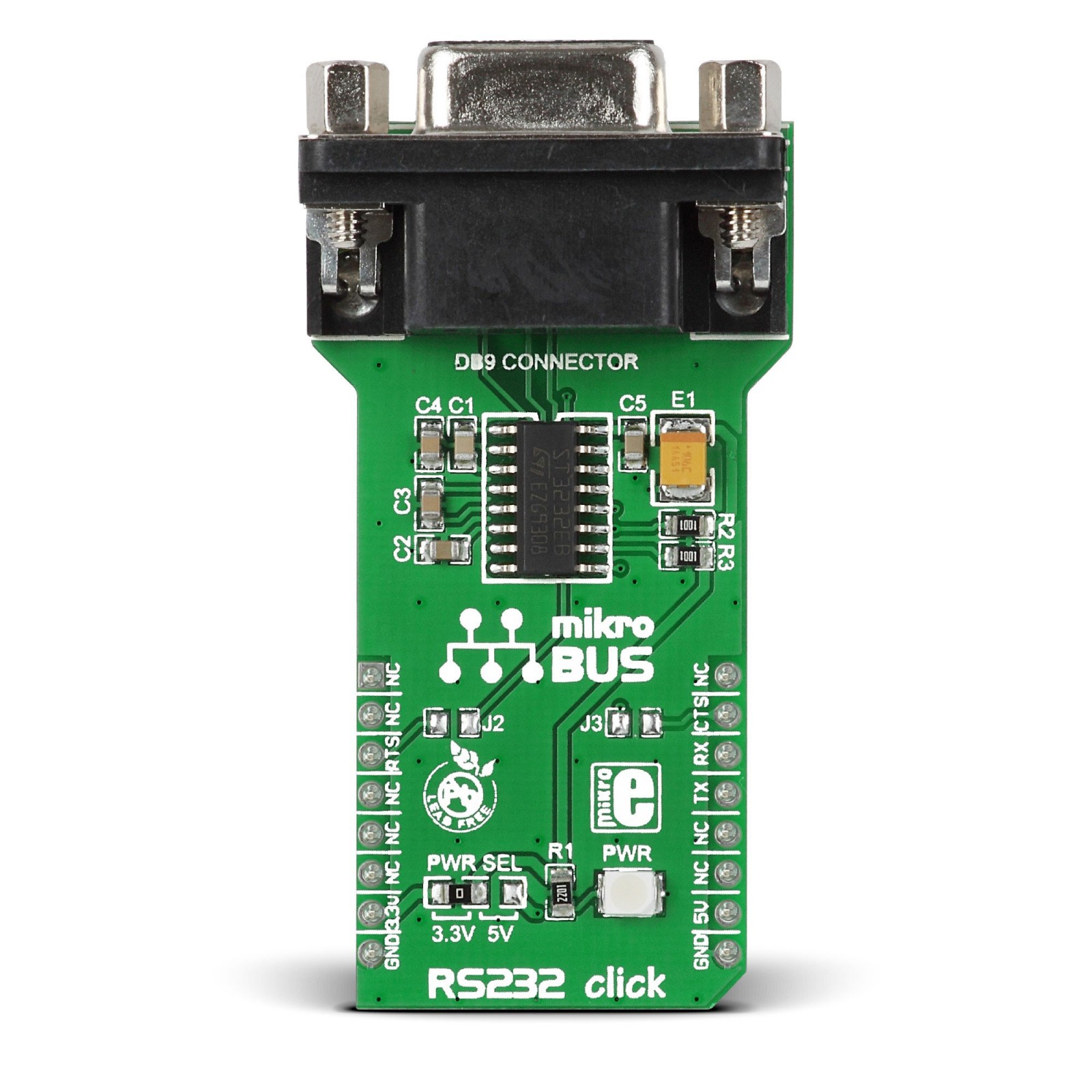
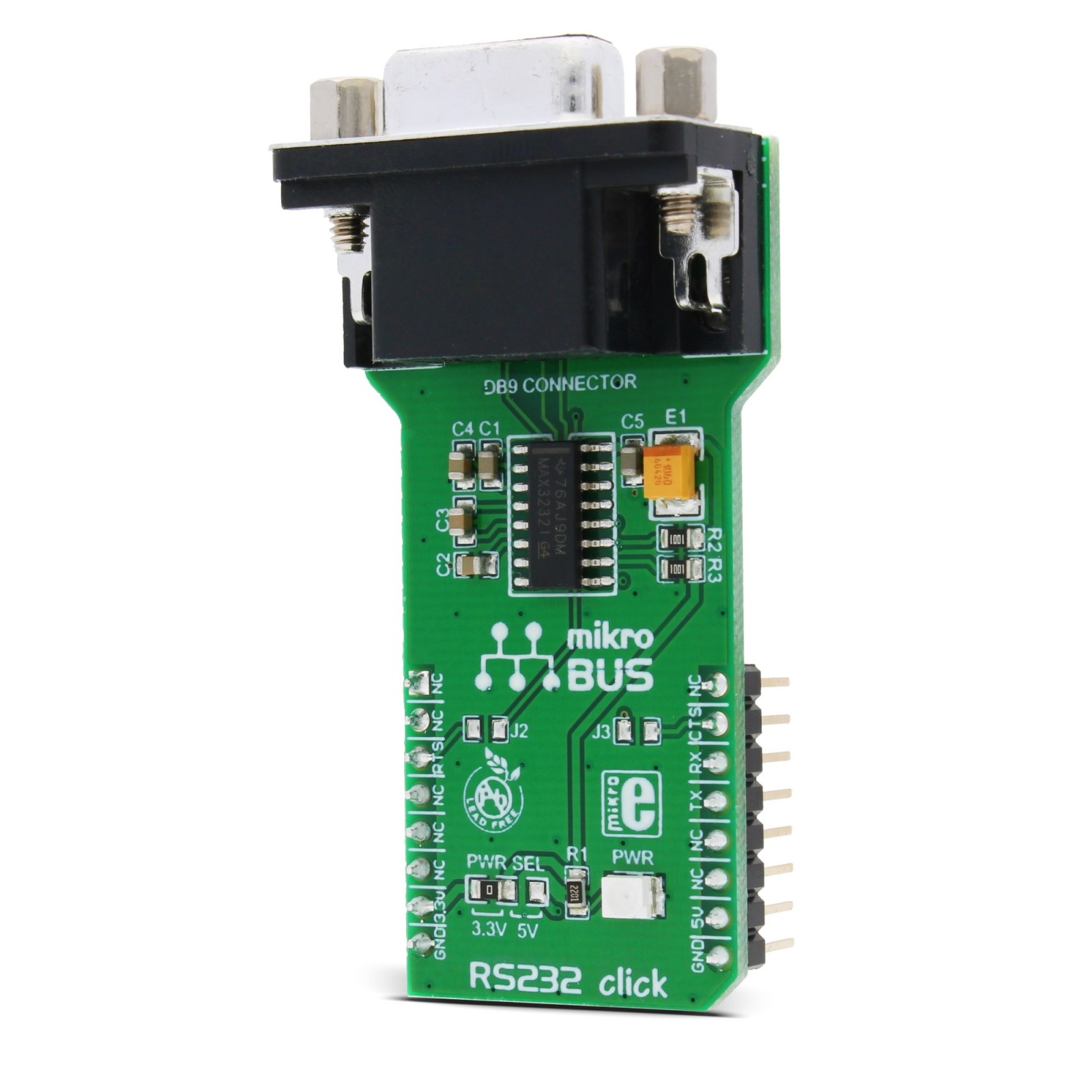
RS232 click provides an interface between the TTL/CMOS logic levels commonly used on microcontrollers and the RS-232 bus. RS-232 is a rather old communication protocol that has survived thanks to its robustness and implementation on many personal computer motherboards. It can still be found on various pieces of DTE and DCE equipment. This Click board™ allows standard type MCUs to communicate through the RS-232 interface via the standard UART bus pins: RX and TX. The RS-232 click utilizes the MAX3232, a 3.0V to 5.5V low power, true RS-232 transceiver, from Maxim Integrated. This device can achieve communication speed up to 232 kbps (EIA/TIA-232).
A number of protection features improve the reliability of this device. It has up to ±15kV ESD protection, ensuring that no electrical discharge damages the circuit on the input side. The Click board™ offers voltage selection for interfacing with both 3.3V and 5V MCUs, allowing fast and reliable RS-232 communication for a wide range of MCUs. It can be used for any application that communicates using the low voltage RS-232 protocol.
How does it work?
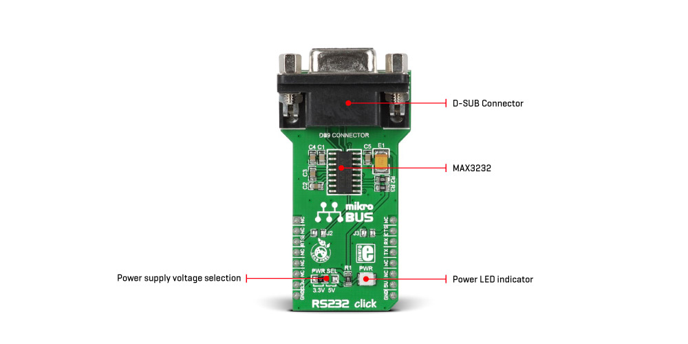
The main component of the RS-232 click is the MAX3232, a 3.0V to 5.5V low power, true RS-232 transceiver, from Maxim Integrated. This IC has two receiver and two transmitter channels, and it is used to bridge the physical differences between the CMOS/TTL signal levels and RS-232 bus levels. While CMOS/TTL signal levels vary from 0V to 5V typically, RS-232 uses the signal levels that range from ±5V, up to ±15 V. Furthermore, the RS-232 equipment is required to withstand short circuit for any voltage, up to ±25V, during an indefinite time interval. To interface CMOS/TTL signal level devices with the RS-232 bus, an adequate RS-232 transceiver, such as the MAX3232 has to be used. MAX3232 IC uses two internal charge pumps to obtain required driving levels of ±5V on its transceiver sections.
This Click board™ offers two inputs and two outputs which feature the CMOS/TTL logic levels. These lines can be used to either drive the RS-232 bus or receive the incoming data from the bus. Receivers convert the RS-232 signals to MCU acceptable UART type signal, while transmitters convert the MCU UART signal to RS-232 levels. Therefore one input/output pair is routed to the UART pins of the mikroBUS™, allowing simplified operation by the host MCU, while another pair of input/output signals is routed via the SMD jumpers and it is used as the RTS (Ready To Send) and CTS (Clear To Send). These pins are typically used for the UART communication with the hardware flow control. The jumpers are populated by default.
To achieve required driving levels, MAX3232 transmitters use the charge pumps, which use only two external capacitors for the proper operation. These capacitors, along with the two pull-up resistors, are the only external elements, required by the MAX3232 IC. If the RS-232 bus levels are driven beyond ±5V, these charge pumps are internally disabled. This means that the MAX3232 can drive the RS-232 bus with up to ±5V by itself. The MAX3232 device can maintain 120kbps data rate with the worst-case scenario – load of 3kΩ in parallel with 1000pF, while the typical communication speed goes up to 232 kbps.
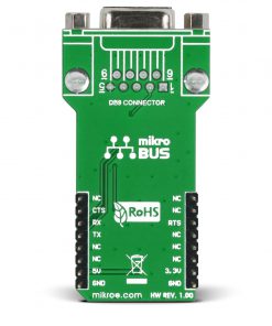
The Click board™ comes equipped with the SUB D connector, typically found on many devices that use the RS-232 interface. This connector can be used to connect the Click board™ directly to the RS-232 bus, offering RX, TX, CTS and RTS RS-232 signals.
RS232 click can be used with both 3.3V and 5V MCUs. There is an SMD jumper labeled as PWR SEL, used to select the power supply voltage level, between 3.3V and 5V.
Specifications
Type
RS232
Applications
Simple solution for adding RS232 connectivity to your device
On-board modules
RS232 DB9 port and a MAX3232 IC
Key Features
Jumper positions for connecting RTS (J2) and CTS (J3) lines
Interface
UART,GPIO
Compatibility
mikroBUS
Click board size
L (57.15 x 25.4 mm)
Input Voltage
3.3V or 5V
Pinout diagram
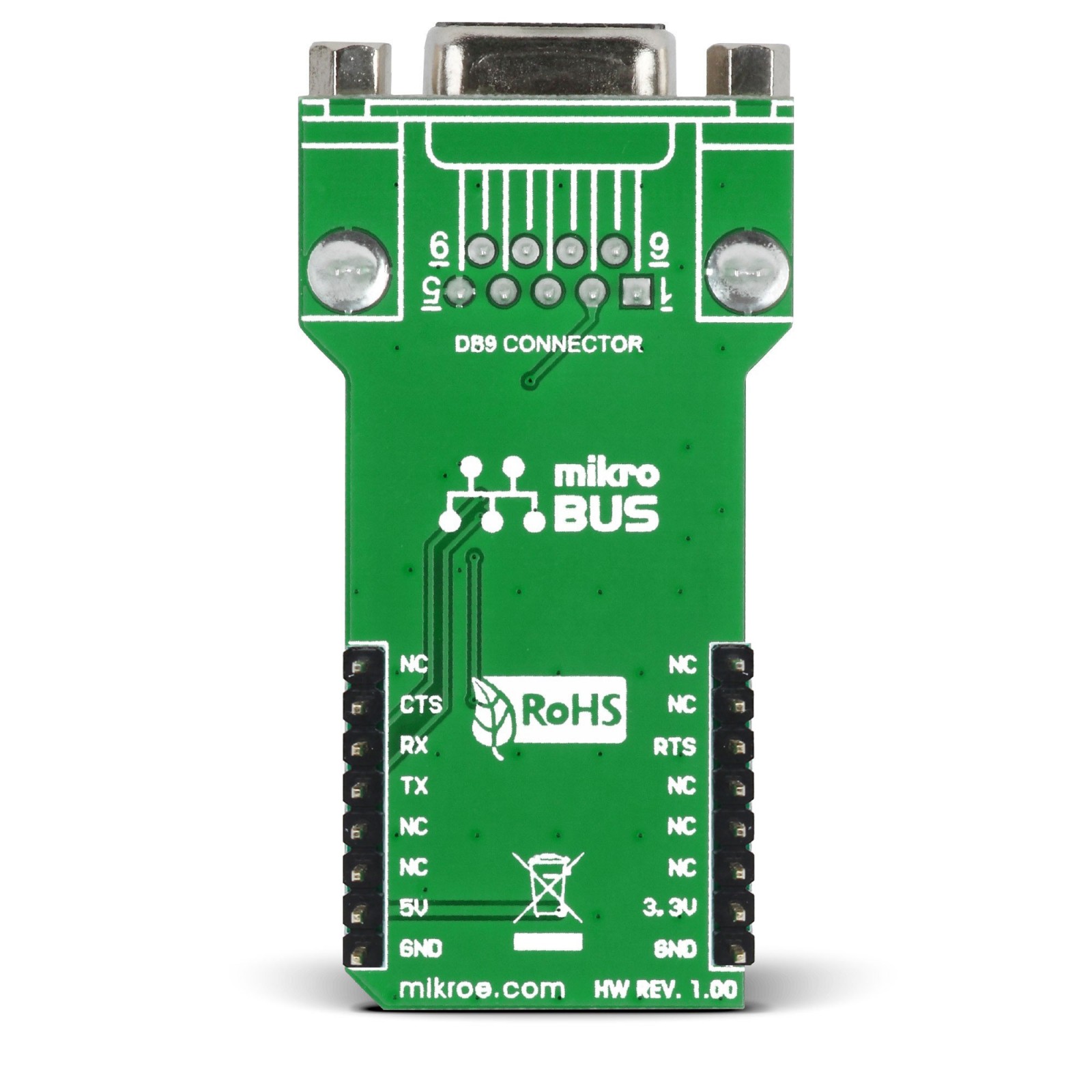
This table shows how the pinout on RS232 click corresponds to the pinout on the mikroBUS™ socket (the latter shown in the two middle columns).
Onboard settings and indicators
Label | Name | Default | Description |
---|---|---|---|
LD1 | PWR | – | Power LED indicator |
J2 | J2 | Populated | RTS signal jumper, allows RTS signal to be routed to the RS-232 D-SUB connector |
J3 | J3 | Populated | CTS signal jumper, allows CTS signal to be routed to the RS-232 D-SUB connector |
CN1 | DB9 | – | Standard RS-232 SUB-D 9-pin connector |
Software support
We provide a library for RS232 click on our Libstock page, as well as a demo application (example), developed using MikroElektronika compilers and mikroSDK. The provided click library is mikroSDK standard compliant. The demo application can run on all the main MikroElektronika development boards.
Library Description
This library provides generic functions for working with the Click board™.
Key functions:
void rs232_writeByte(uint8_t input)
- Writes a Single Byte.uint8_t rs232_readByte()
- Reads a Single Byte.uint8_t ras232_byteReady()
- Checks if a new byte has been received.
Examples Description
The application is composed of three sections:
- System Initialization – Initializes UART module.
- Application Initialization – Driver intialization.
- Application Task – (code snippet) – Checks if new data byte has received in the RX buffer (ready for reading), and if ready than reads one byte from the RX buffer. In second case application task writes message data via UART.
void applicationTask() { char tmp; uint8_t rdyFlag; // RECEIVER - UART polling rdyFlag = rs232_byteReady(); if (1 == rdyFlag) { tmp = rs232_readByte(); mikrobus_logWrite( &tmp, _LOG_BYTE ); } // TRANSMITER - TX each 2 sec /* for (tmp = 0; tmp < 9; tmp++) { rs232_writeByte( MESSAGE_DATA[tmp] ); mikrobus_logWrite( "MESSAGE SENT", _LOG_LINE ); } Delay_ms(2000); */ }
The full application code, and ready to use projects can be found on our Libstock page.
Other mikroE Libraries used in the example:
- UART
Additional notes and information
Depending on the development board you are using, you may need USB UART click, USB UART 2 click or RS232 click to connect to your PC, for development systems with no UART to USB interface available on the board. The terminal available in all MikroElektronika compilers, or any other terminal application of your choice, can be used to read the message.
mikroSDK
This click board is supported by mikroSDK - MikroElektronika Software Development Kit. To ensure proper operation of mikroSDK compliant click board demo applications, mikroSDK should be downloaded from the LibStock and installed for the compiler you are using.
For more information about mikroSDK, visit the official page.