How does it work?
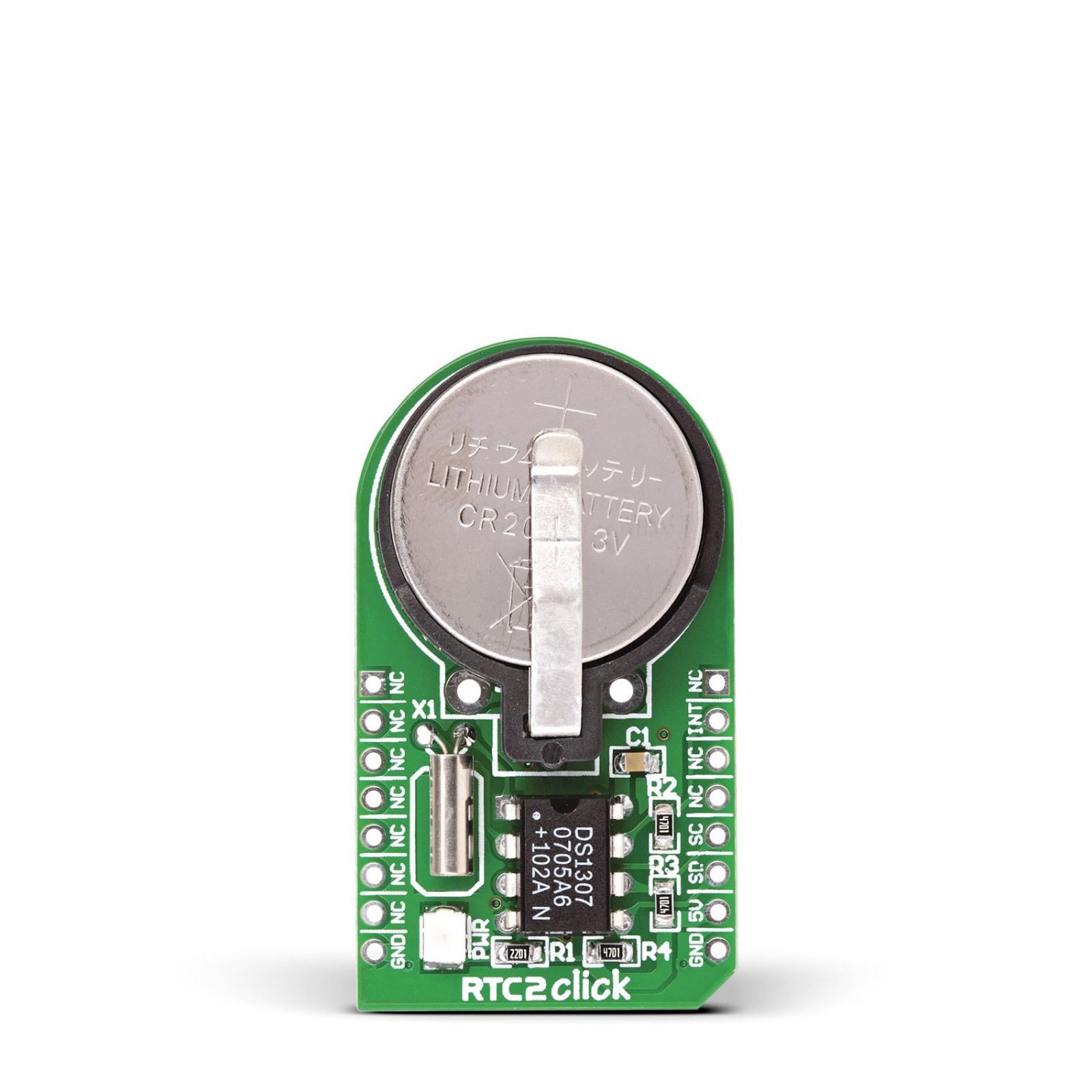
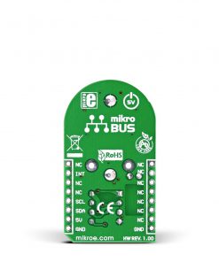
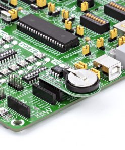
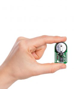
RTC 2 Click is based on the DS1307, a 64×8 serial I2C Real-Time clock from Analog Devices. It is a low-power, full binary-coded decimal (BCD) clock/calendar with 56 bytes of NV SRAM. The end of months is automatically adjusted for months with fewer than 31 days, including corrections for the leap year. The clock can operate in either a 24-hour or 12-hour format with AM/PM indicator. The RTC has a built-in power-sense circuit that automatically switches to the backup power supply when it detects a power failure. The RTC 2 comes equipped with a 3V/230mA lithium battery, ensuring timekeeping continues even when the main power supply goes OFF.
The RTC 2 Click uses an I2C 2-Wire interface for communication with the host MCU, with a clock rate of up to 400KHz. The interrupt INT pin of this Click board™ outputs one of four square-wave frequencies (1Hz, 4KHz, 8KHz, and 32KHz). When enabled, it outputs frequency depending on values set in configuration bits.
This Click board™ can be operated only with a 5V logic voltage level. The board must perform appropriate logic voltage level conversion before using MCUs with different logic levels. However, the Click board™ comes equipped with a library containing functions and an example code that can be used, as a reference, for further development.
Specifications
Type
RTC
Applications
Can be used for developing the IoT, wearable and portable devices, logging devices, industrial and health-related time metering applications, and all the other applications that require an accurate time base for various purposes
On-board modules
DS1307 – 64×8 serial I2C Real-Time clock from Analog Devices
Key Features
Tracks hours, minutes, seconds, days, months, years, and weekdays, with leap year compensation until 2100, battery backup support, 56 bytes of battery-backed RAM, square-wave output, and more
Interface
GPIO,I2C
Feature
No ClickID
Compatibility
mikroBUS™
Click board size
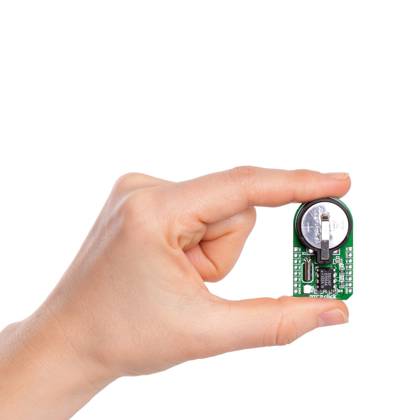
M (42.9 x 25.4 mm)
Input Voltage
5V
Pinout diagram
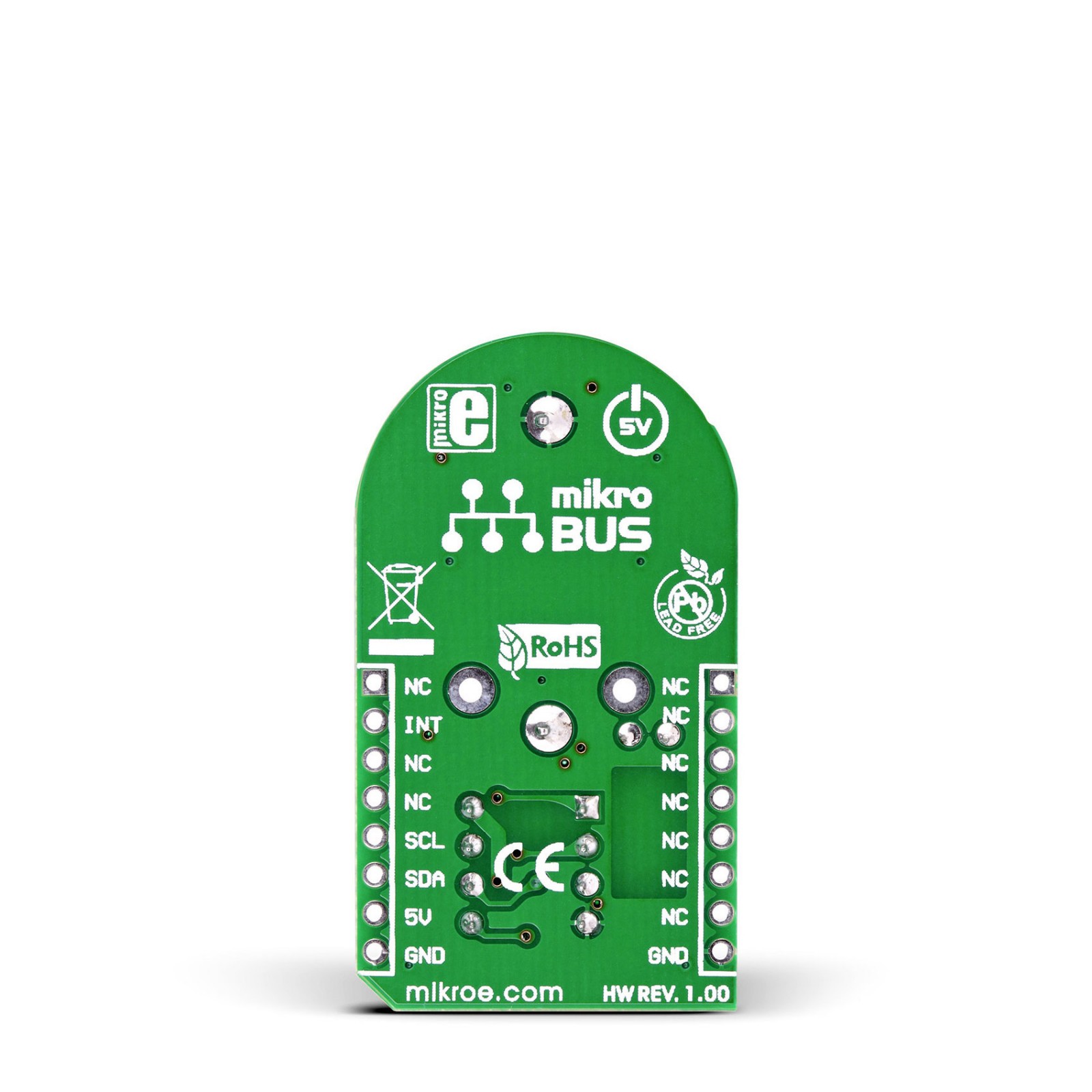
This table shows how the pinout on RTC 2 Click corresponds to the pinout on the mikroBUS™ socket (the latter shown in the two middle columns).
Onboard settings and indicators
Label | Name | Default | Description |
---|---|---|---|
– | PWR | – | Power LED Indicator |
RTC 2 Click electrical specifications
Description | Min | Typ | Max | Unit |
---|---|---|---|---|
Supply Voltage | – | 5 | – | V |
Memory Size | – | – | 56 | byte |
Date Format | YY-MM-DD |
Software Support
We provide a library for the RTC2 Click as well as a demo application (example), developed using MIKROE compilers. The demo can run on all the main MIKROE development boards.
Package can be downloaded/installed directly from NECTO Studio Package Manager (recommended), downloaded from our LibStock™ or found on Mikroe github account.
Library Description
This library contains API for RTC2 Click driver.
Key functions
-
Generic read byte of data function.
-
Generic write byte of data function.
-
Enable counting function.
Example Description
This application give time and day information.
void application_task ( void )
{
rtc2_get_time( &rtc2, &time_hours, &time_minutes, &time_seconds );
rtc2_get_date( &rtc2, &day_of_the_week, &date_day, &date_month, &date_year );
if ( time_seconds_new != time_seconds )
{
log_printf( &logger, " Time : " );
display_log_uart( time_hours );
log_printf( &logger, ":" );
display_log_uart( time_minutes );
log_printf( &logger, ":" );
display_log_uart( time_seconds );
log_printf( &logger, "" );
display_day_of_the_week( day_of_the_week );
log_printf( &logger, " Date: " );
display_log_uart( date_day );
log_printf( &logger, "." );
display_log_uart( date_month );
log_printf( &logger, "." );
log_printf( &logger, "20" );
display_log_uart( date_year );
log_printf( &logger, "." );
log_printf( &logger, "-------------------" );
time_seconds_new = time_seconds;
}
}
The full application code, and ready to use projects can be installed directly from NECTO Studio Package Manager (recommended), downloaded from our LibStock™ or found on Mikroe github account.
Other Mikroe Libraries used in the example:
- MikroSDK.Board
- MikroSDK.Log
- Click.Rtc2
Additional notes and informations
Depending on the development board you are using, you may need USB UART click, USB UART 2 Click or RS232 Click to connect to your PC, for development systems with no UART to USB interface available on the board. UART terminal is available in all MIKROE compilers.
mikroSDK
This Click board™ is supported with mikroSDK – MIKROE Software Development Kit. To ensure proper operation of mikroSDK compliant Click board™ demo applications, mikroSDK should be downloaded from the LibStock and installed for the compiler you are using.
For more information about mikroSDK, visit the official page.