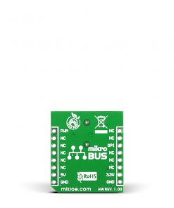
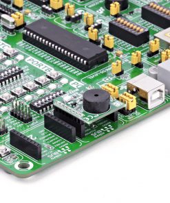
BUZZ Click
R190.00 R110.00 ex. VAT
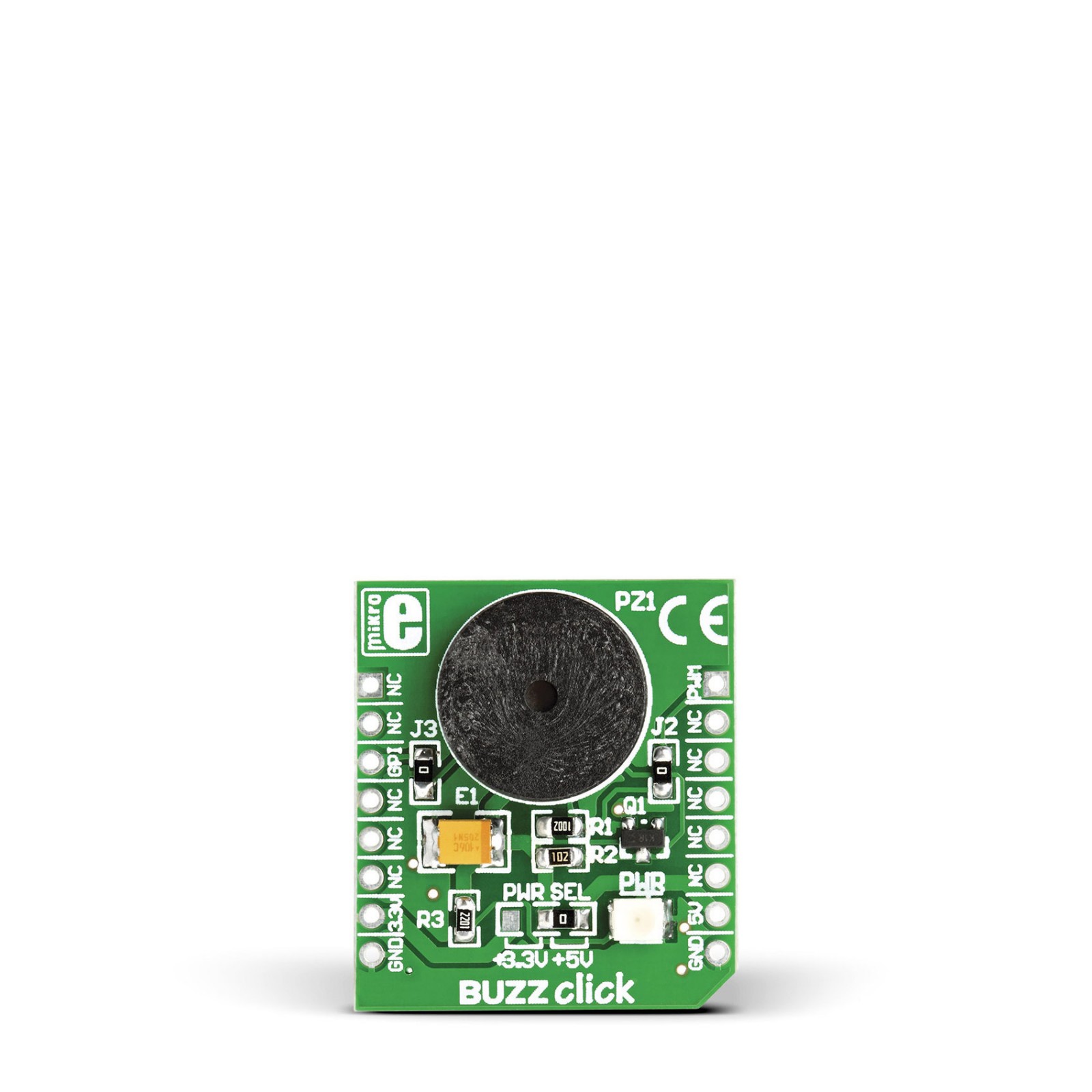
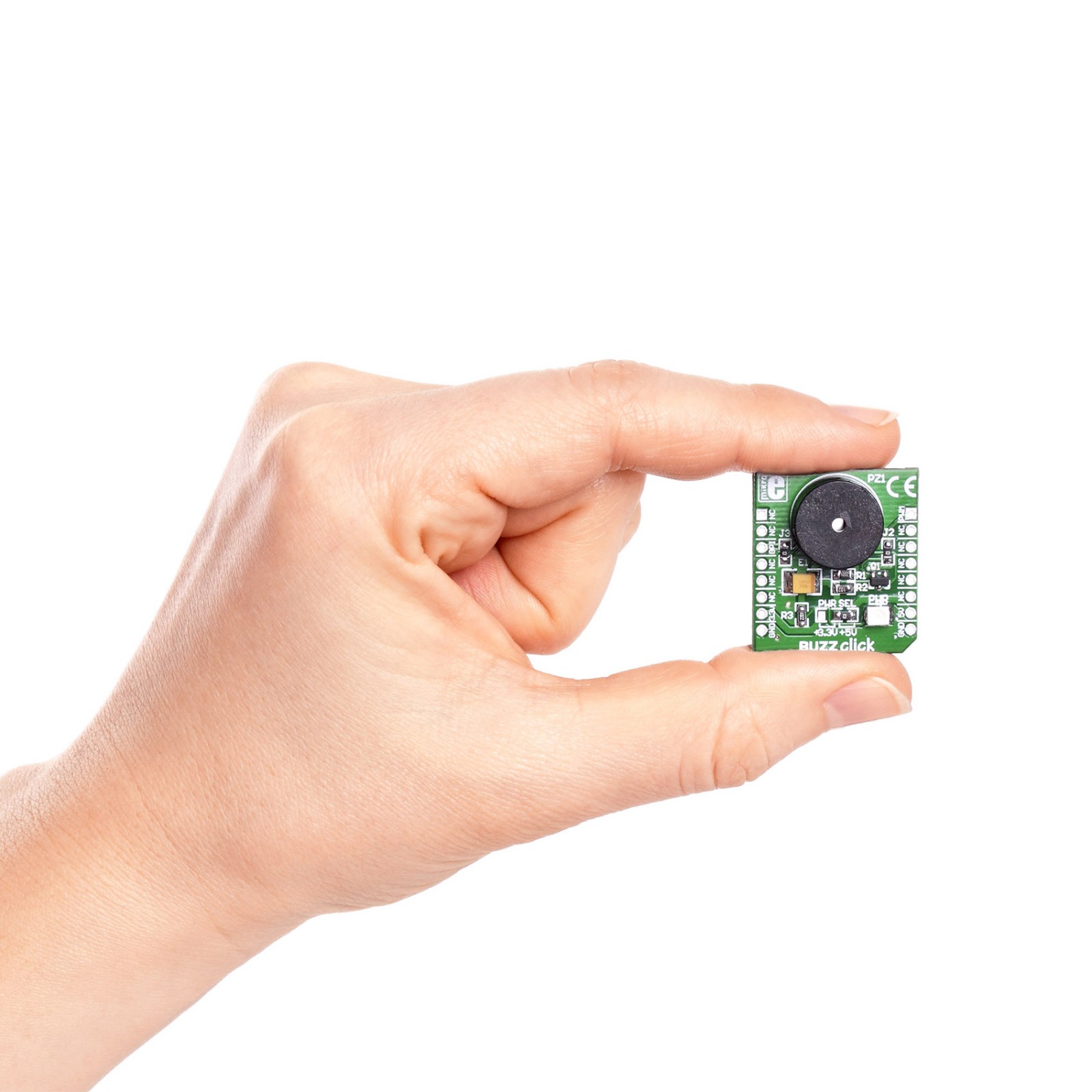
Buzz Click is a compact add-on board with a piezo speaker capable of emitting an audio signal. This board features the EPT-14A4005P, a piezoelectric transducer from Sanco Electronics. It is an electronic device that can be used to produce a tone, alarm, or sound. It has reasonable loudness with a minimum of 88dB at 10cm from the speaker. This Click board™ makes the perfect solution for the development of a variety of audio signalization feature applications, including medical systems, alarm clocks, home appliances, and security devices.
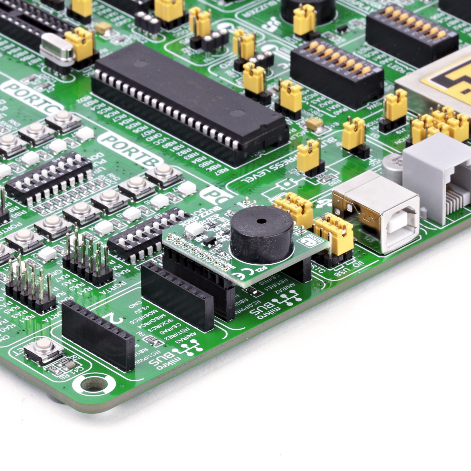
Buzz Click is supported by a mikroSDK compliant library, which includes functions that simplify software development. This Click board™ comes as a fully tested product, ready to be used on a system equipped with the mikroBUS™ socket.
Stock: 1 available immediately.
How does it work?
Buzz Click is based on the EPT-14A4005P, a piezoelectric transducer from Sanco Electronics. It uses a DC voltage to produce an audio signal while drawing a maximum current of 2mA from a wide operating voltage, in this case, 3.3V or 5V. As its name suggests, a piezo buzzer’s core comprises the piezoelectric ceramic element and a metal plate held together by an adhesive. When a DC is passed through, the piezoceramic element contracts and expands, which causes a vibration that produces sound waves. The buzzer has a resonant frequency of 4000Hz, at which the buzzer vibrates, thus making a sound. The buzzer is 13.8×6.8mm in dimensions, and besides this Click board™, it can be bought separately from MIKROE.
The onboard buzzer driver can be controlled by either a digital GPI pin or a PWM line of a mikroBUS™ socket. Users can create a sound using the Sound library supported in MIKROE compilers or utilize the microcontroller’s internal PWM module to generate the signal for the buzzer. Signal frequency determines the sound pitch, and the duty cycle determines the amplitude (sound volume). Both GPI and PWM lines are connected to the buzzer by default. The user can separate one of the lines by removing the corresponding jumper (J2 or J3).
This Click board™ can operate with either 3.3V or 5V logic voltage levels selected via the PWR SEL jumper. This way, both 3.3V and 5V capable MCUs can use the communication lines properly. However, the Click board™ comes equipped with a library containing easy-to-use functions and an example code that can be used, as a reference, for further development.
Specifications
Type
Speakers
Applications
Can be used for the development of a variety of audio signalization feature applications, including medical systems, alarm clocks, home appliances, and security devices
On-board modules
EPT-14A4005P – piezoelectric transducer from Sanco Electronics
Key Features
4KHz resonant frequency, controlled by a digital pin or a PWM line, reasonable loudness with a minimum of 88dB at 10cm from the speaker, 2mA maximum current, high performance, and more
Interface
GPIO,PWM
Feature
No ClickID
Compatibility
mikroBUS™
Click board size
S (28.6 x 25.4 mm)
Input Voltage
3.3V or 5V
Pinout diagram
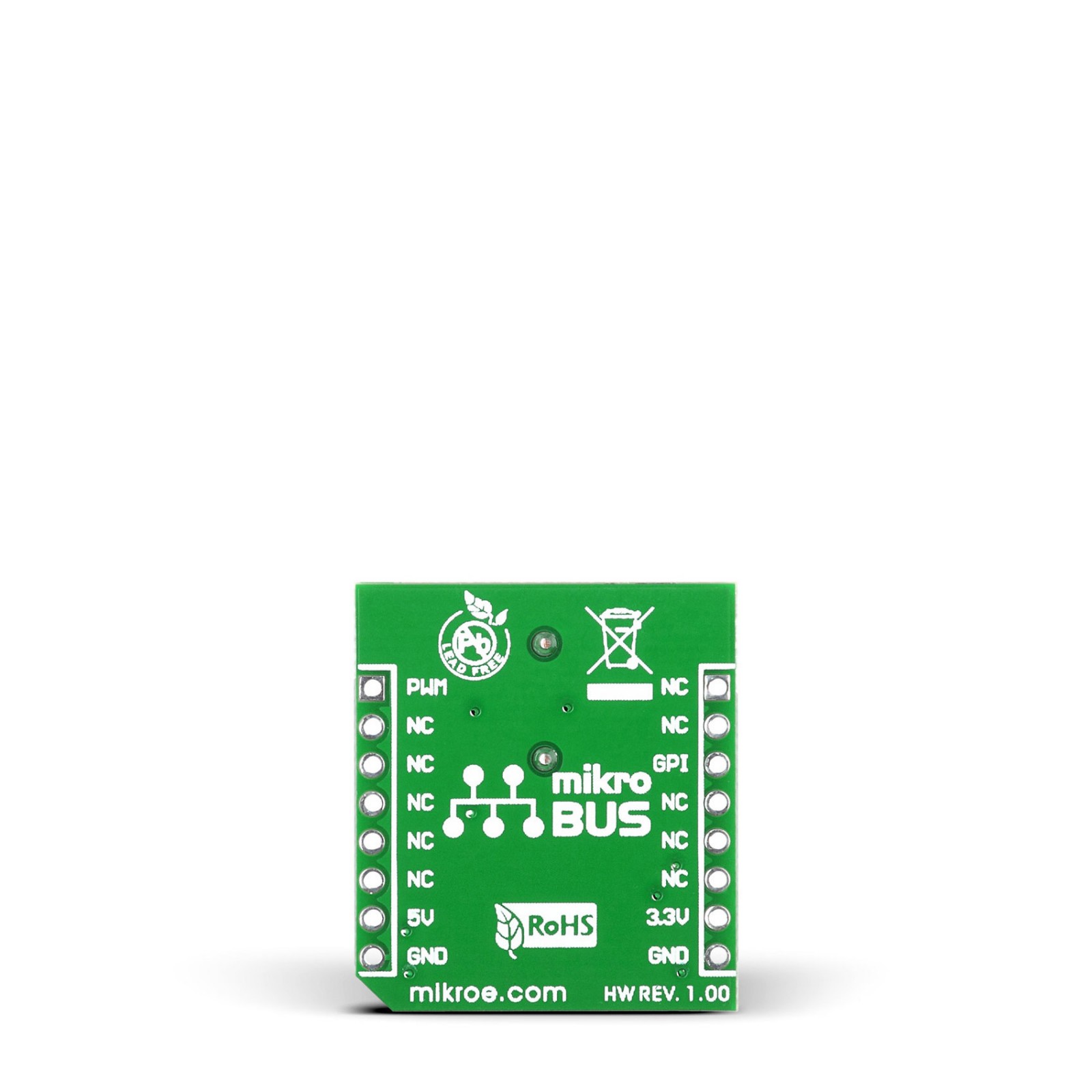
This table shows how the pinout on BUZZ Click corresponds to the pinout on the mikroBUS™ socket (the latter shown in the two middle columns).
Onboard settings and indicators
| Label | Name | Default | Description |
|---|---|---|---|
| LD1 | PWR | – | Power LED Indicator |
| J1 | PWR SEL | Right | Power/Logic Level Voltage Selection 3V3/5V: Left position 3V3, Right position 5V |
| J2 | – | Populated | PWM Control Signal Selection |
| J3 | – | Populated | Digital Control Signal Selection |
BUZZ Click electrical specifications
| Description | Min | Typ | Max | Unit |
|---|---|---|---|---|
| Supply Voltage | 3.3 | – | 5 | V |
| Resonant Frequency | – | 4 | – | kHz |
Software Support
We provide a library for the BUZZ Click as well as a demo application (example), developed using MIKROE compilers. The demo can run on all the main MIKROE development boards.
Package can be downloaded/installed directly from NECTO Studio Package Manager (recommended), downloaded from our LibStock™ or found on Mikroe github account.
Library Description
This library contains API for BUZZ Click driver.
Key functions
-
buzz_set_duty_cycleThis function sets the PWM duty cycle in percentages ( Range[ 0..1 ]). -
buzz_pwm_stopThis function stops the PWM moudle output. -
buzz_pwm_startThis function starts the PWM moudle output. -
buzz_play_soundThis function plays sound on buzzer.
Example Description
This example demonstrates the use of Buzz click boards.
 void application_task ( void ) {
     log_printf( &logger, "Playing the Imperial March melody ...rn" );
     imperial_march( );
     Delay_ms( 10000 );
 }
The full application code, and ready to use projects can be installed directly from NECTO Studio Package Manager (recommended), downloaded from our LibStock™ or found on Mikroe github account.
Other Mikroe Libraries used in the example:
- MikroSDK.Board
- MikroSDK.Log
- Click.BUZZ
Additional notes and informations
Depending on the development board you are using, you may need USB UART click, USB UART 2 Click or RS232 Click to connect to your PC, for development systems with no UART to USB interface available on the board. UART terminal is available in all MIKROE compilers.
mikroSDK
This Click board™ is supported with mikroSDK – MIKROE Software Development Kit. To ensure proper operation of mikroSDK compliant Click board™ demo applications, mikroSDK should be downloaded from the LibStock and installed for the compiler you are using.
For more information about mikroSDK, visit the official page.
Resources
Downloads
| Weight | 28 g |
|---|---|
| Brand | MikroElektronika |

