Vacuum Click
R1,250.00 ex. VAT
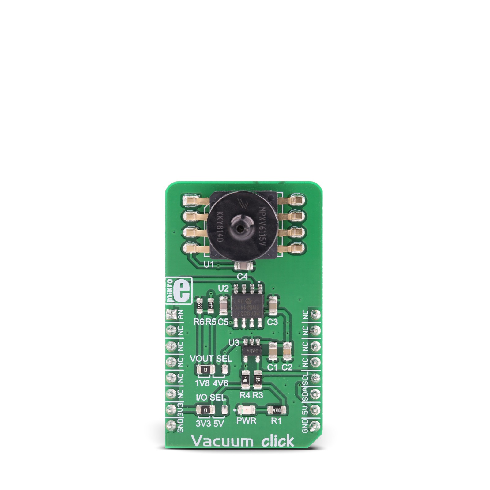
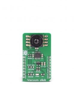
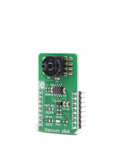
Vacuum click is an accurate vacuum pressure sensing click board™, capable of measuring absolute pressure values down to -115kPa. This click board™ utilizes the MPXV6115V, a very accurate vacuum pressure sensor. This piezo-resistive transducer is a monolithic sensor which combines advanced MEMS manufacturing technology with the on-chip signal processing, offering very accurate readings and very low drift over temperature. The sensor outputs an analog voltage, linearly dependent on the applied vacuum pressure. This voltage is digitized by an accurate A/D converter and delivered over the I2C interface.
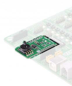
Vacuum click is supported by a mikroSDK compliant library, which includes functions that simplify software development. This Click board™ comes as a fully tested product, ready to be used on a system equipped with the mikroBUS™ socket.
Stock: Lead-time applicable.
| 5+ | R1,187.50 |
| 10+ | R1,125.00 |
| 15+ | R1,062.50 |
| 20+ | R1,022.50 |
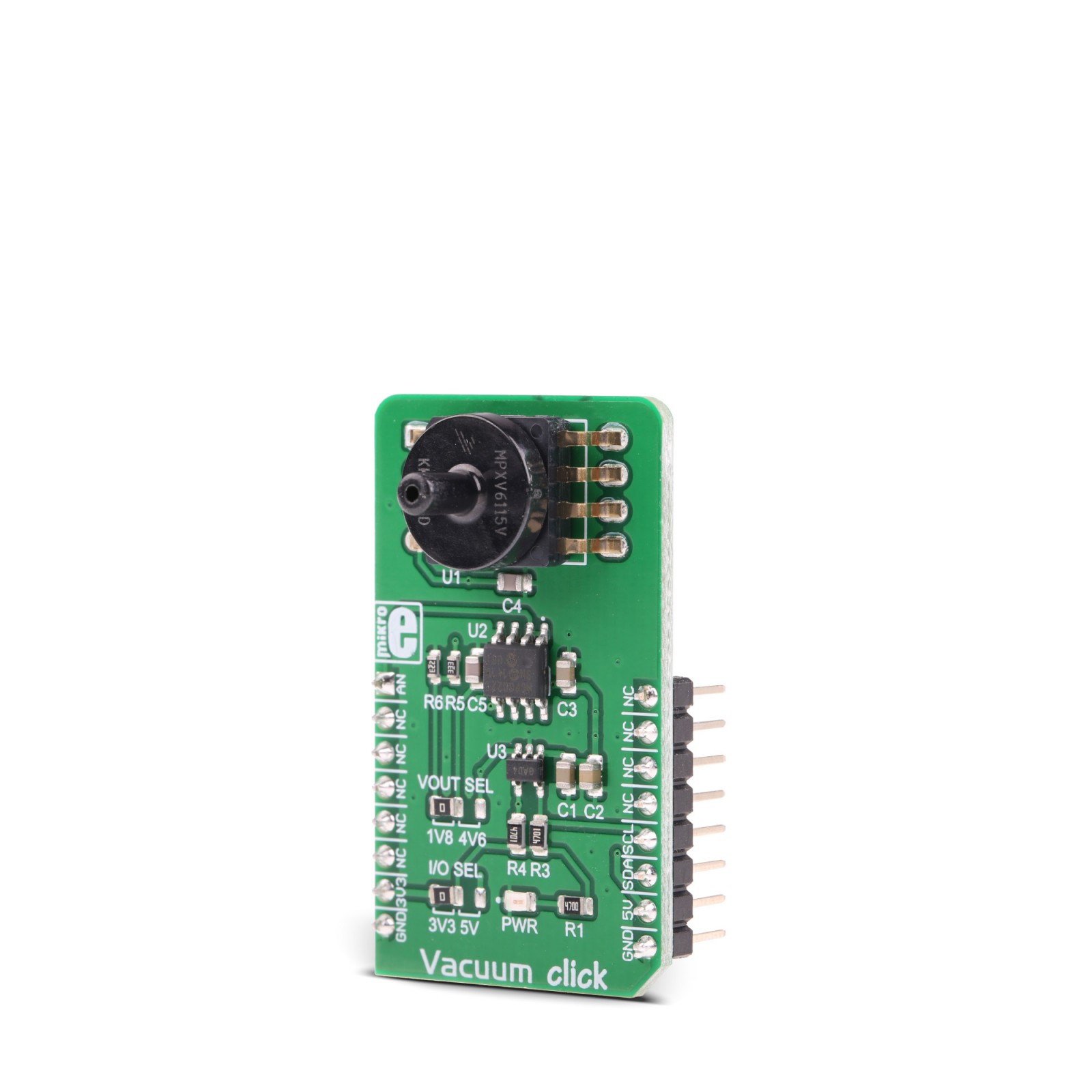
The MPXV6115V sensor is shaped so that a small tube can be attached to it, which simplifies its implementation. This makes the sensor an ideal solution for monitoring the operation of various vacuum pumps, brake boosting parts, and other types of devices that use a vacuum pressure that needs monitoring. The sensor also allows monitoring of a liquid level: as the liquid level drops, a vacuum is formed in a tube immersed in the liquid. By measuring the vacuum pressure in the tube, the liquid level can be easily estimated.
How does it work?
Vacuum click uses a highly advanced monolithic vacuum pressure sensor, labeled as MPXV6115V from NXP. This sensor features the piezo-resistive MEMS sensing element, combined with the application-specific integrated circuit (ASIC) allowing a high degree of linearity, as well as a very low drift over the temperature. The lower part of the sensor contains the necessary sensing elements, while the upper part of the sensor is shaped as a small tube, and it is referred to as “port” in the datasheet. A small rubberized hose can easily be attached to the inlet, so that the vacuum producing counterpart can be securely connected with the sensor. The design of the inlet prevents leakage that might appear if the sealing is not good enough.
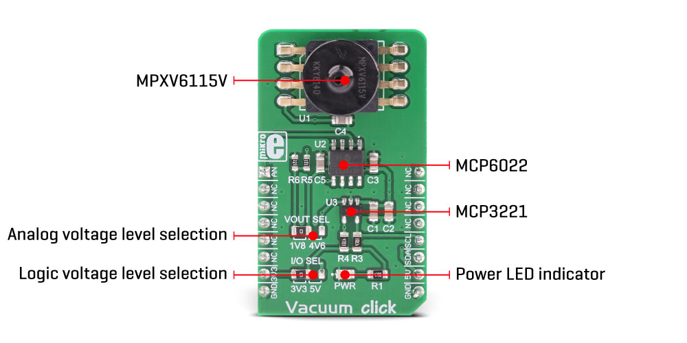
The sensor itself outputs approximately 4.6V DC voltage on its output pin when it is located at the sea-level pressure. As the pressure decreases, the voltage drops towards 0V. The ASIC ensures that the voltage drop is linear with the pressure. The MPXV6115V datasheet offers a diagram that illustrates the output voltage vs pressure dependency.
The second section of the Click board™ is the converter section, and it contains an Analog-to-Digital converter (ADC) IC. Vacuum click utilizes the MCP3221, a 12-bit successive approximation ADC with I2C Interface, from Microchip. It is used to sample the output voltage from the sensor, allowing the digitized value to be retrieved over the I2C interface. The ADC uses 5V power rail of the mikroBUS™ as a voltage reference. The relation between the ADC value at the I2C interface, and the voltage on the output pin, is given by the following formula:
VOUT = 5/4096 x VAL
Where VOUT is the output voltage of the sensor and VAL is the 12-bit ADC value. However, the Click board™ is supplied with the library that contains functions which automatically calculate values, providing vacuum percentage as the output.
The voltage output of the sensor is also directly available on the AN output and it is buffered with an operational amplifier. It can be used if the 12-bit ADC accuracy is not high enough, or if some other type of output voltage converter has to be used. The AN pin of the mikroBUS™ offers two voltage output settings, selectable by the SMD jumper labeled as VOUT. The default position (1V8) routes the output voltage from the sensor to a voltage divider, reducing the maximum output value at the AN pin. The maximum voltage value is approximately 1.85 V in this case, when used at the sea level. This setting prevents damage in the case when the host MCU is not 5V tolerant. If the host MCU has 5V tolerant pins, the full voltage output can be used. If the VOUT jumper is soldered at the 4V6 position, the signal will not be routed to the voltage divider, so the voltage at the AN pin of the mikroBUS™ can swing up to the maximum voltage level available from the sensor. This voltage ranges up to 4.6V at sea level (101.325 kPa). Please note that the output can also increase above this value when a positive pressure is applied to the sensor (which is not advised).
Another onboard jumper labeled as I/O SEL offers a selection of the I2C communication voltage levels. This jumper can be used to interface the Click board™ both with the 3.3V and 5V MCUs, allowing a wide range of different MCUs to be used with the Click board™.
Specifications
Type
Pressure
Applications
It can be used for monitoring vacuum percentage in various hydraulic or other type of devices that rely on a vacuum percentage for a proper operation: vacuum pumps, braking assemblies and similar
On-board modules
MPXV6115V, a highly advanced, integrated monolithic vacuum sensor, labeled as MPXV6115V, from NXP; MCP3221, a 12bit D/A converter with I2C Interface, from Microchip; MCP6022, a rail-to-rail operational amplifier, from Microchip
Key Features
High measurement accuracy, low drift over temperature, specially designed inlet port for simplified sealing in applications, very linear vacuum percentage readings, available in 12-bit format over I2C or via the buffered analog pin, and more
Interface
Analog,I2C
Feature
No ClickID
Compatibility
mikroBUS™
Click board size
M (42.9 x 25.4 mm)
Input Voltage
3.3V or 5V
Pinout diagram
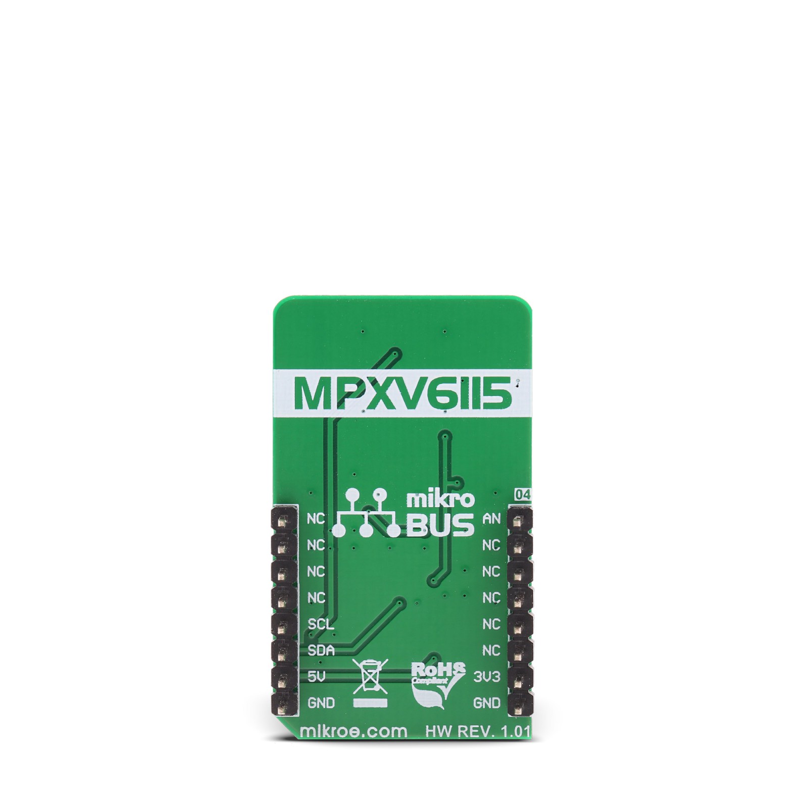
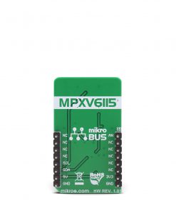
This table shows how the pinout on Vacuum click corresponds to the pinout on the mikroBUS™ socket (the latter shown in the two middle columns).
Onboard jumpers and settings
| Label | Name | Default | Description |
|---|---|---|---|
| LD1 | PWR | – | Power LED indicator |
| JP1 | VOUT SEL | Left | Analog voltage level selection: left position 1.8V, right position 4.6V |
| JP2 | I/O SEL | Left | Logic voltage level selection: left position 3.3V, right position 5V |
Software support
We provide a library for the Vacuum click on our LibStock page, as well as a demo application (example), developed using MikroElektronika compilers. The demo can run on all the main MikroElektronika development boards.
Library Description
The library initializes and defines the I2C bus driver.
The library includes the function for reading ADC data and the function for converting ADC value to the percentage of Vacuum and pressure in mBar.
The user also has the function for sensor calibration.
Key functions :
void vacuum_calibration()- Sensor calibration
uint16_t vacuum_readData()- The function for reads 12 bit ADC data
float vacuum_getVoltage()- The function for converting ADC value to pressure data
float vacuum_getPercentageOfVacuum()- The function for converting ADC value to percentage of Vacuum
Example description
The application is composed of three sections :
- System Initialization – Initializes I2C module
- Application Initialization – Initialization driver init and calibration of the chip to start measuring
- Application Task – (code snippet) – Reads vacuum percentage that sensor reads
void applicationTask()
{
 mikrobus_logWrite("Vacuum (voltage) : ", _LOG_TEXT);
 Vacuum_volt = vacuum_getVoltage();
 FloatToStr(Vacuum_volt, demoText);
 mikrobus_logWrite(demoText, _LOG_TEXT);
 mikrobus_logWrite(" V", _LOG_LINE);

 mikrobus_logWrite("Percentage of vacuum: ", _LOG_TEXT);
 Vacuum = vacuum_getPercentageOfVacuum();
 FloatToStr(Vacuum, demoText);
 mikrobus_logWrite(demoText, _LOG_LINE);

 mikrobus_logWrite(" ", _LOG_LINE);
 Delay_ms(300);
}
The full application code, and ready to use projects can be found on our LibStock page.
Other mikroE Libraries used in the example:
- I2C
Additional notes and information
Depending on the development board you are using, you may need USB UART click, USB UART 2 click or RS232 click to connect to your PC, for development systems with no UART to USB interface available on the board. The terminal available in all MikroElektronika compilers, or any other terminal application of your choice, can be used to read the message.
mikroSDK
This click board is supported with mikroSDK – MikroElektronika Software Development Kit. To ensure proper operation of Click board™ demo applications, the mikroSDK package should be downloaded from the LibStock and installed for the compiler of your choice. For more information about mikroSDK, visit the official page.
Resources
Downloads
| Weight | 19 g |
|---|---|
| Brand | MikroElektronika |

